
Battery explosion-proof circuit and battery charging circuit

A battery charging and circuit technology, applied in battery circuit devices, circuit devices, emergency protection circuit devices, etc., can solve problems such as overheating and damage of electronic switches, secondary damage of batteries, failure to limit load current, etc.

Active Publication Date: 2014-07-30
BEIJING TOCEL ELECTRONICS
View PDF7 Cites 7 Cited by
  • Summary
  • Abstract
  • Description
  • Claims
  • Application Information

AI Technical Summary

Problems solved by technology

[0004] For this reason, the technical problem to be solved by the present invention is that the current limiting circuit in the prior art may cause secondary damage to the battery and may not be able to limit the load current and cause the electronic switch to be overheated and damaged, thereby proposing a battery explosion-proof circuit and battery charging circuit

Method used


Image

  • Battery explosion-proof circuit and battery charging circuit
  • Battery explosion-proof circuit and battery charging circuit
  • Battery explosion-proof circuit and battery charging circuit

Examples


Embodiment 1

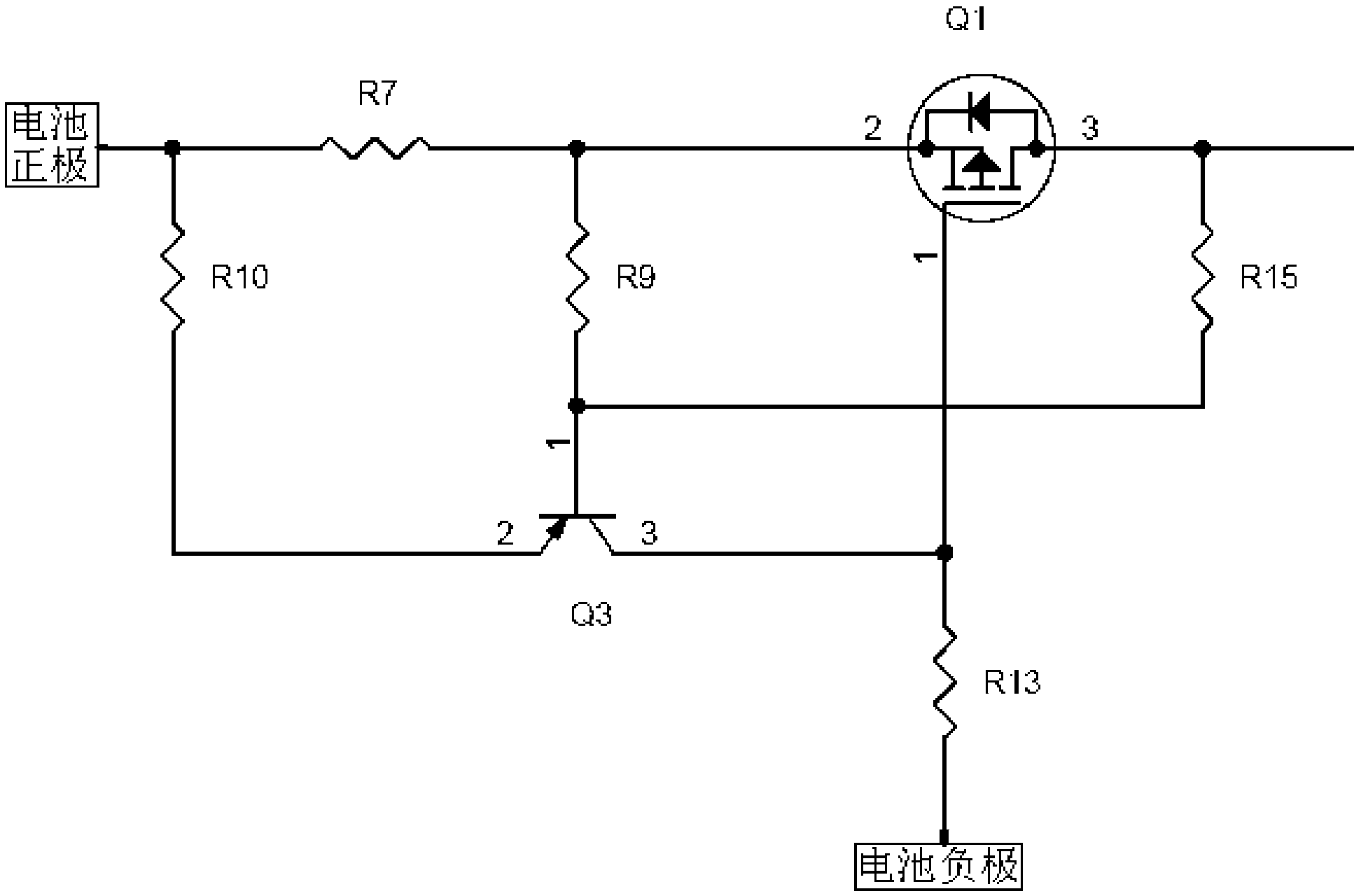
[0053] As a battery explosion-proof circuit according to an embodiment of the present invention, such as figure 2 As shown, the power electronic switch Q1 shown in the figure is a P-channel enhancement MOS transistor, and the feedback control switch Q3 is a PNP transistor. The battery explosion-proof circuit of this embodiment includes:

[0054] A current limiting module, the current limiting module includes an input terminal and an output terminal, the input terminal of the current limiting module is connected to the positive pole of the battery.

[0055] The current limiting module specifically includes: a current limiting resistor R7, a protection resistor R10, a control resistor R9, a feedback resistor R15, a control resistor R13, a power electronic switch Q1 and a feedback control switch Q3, wherein,

[0056] Both the power electronic switch Q1 and the feedback control switch Q3 include an input terminal, an output terminal and a control terminal, and when the relative ...

Embodiment 2

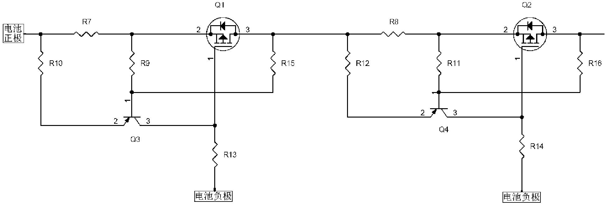
[0066] like image 3 As shown, as an explosion-proof circuit for a battery according to an embodiment of the present invention, on the basis of Embodiment 1 above, there are two current limiting modules, and the two current limiting modules are connected in series.

[0067] The battery explosion-proof circuit provided by the present invention is equipped with two current limiting modules, which further ensures the reliability of the circuit. When one of the current limiting modules fails, it can still ensure that the circuit can accurately limit the load current.

Embodiment 3

[0069] An explosion-proof circuit for a battery as an embodiment of the present invention, on the basis of Embodiment 1 or 2 above, further includes an overvoltage protection module, the overvoltage protection module includes an input terminal, an output terminal and a ground terminal, Both the input terminal and the output terminal of the overvoltage protection module are connected to the output terminal of the current limiting module, and the ground terminal of the overvoltage protection module is connected to the negative pole of the battery.

[0070] The battery explosion-proof circuit provided by the present invention is provided with an overvoltage protection module to prevent excessive high voltage from being generated in the circuit from damaging components.


PUM


Abstract

The invention relates to a battery explosion-proof circuit and a battery charging circuit. When load short circuit occurs, voltage of the output end of an electronic power switch Q1 approximates to voltage of a battery negative pole, and a feedback control switch Q3 is switched on by controlling voltage division of a resistor R9 and a feedback resistor R15. Due to the breakover of the feedback control switch Q3, continuously raising high level is produced on a control resistor R13, the electronic power switch Q1 can be in a cut-off state, load current is cut off, and the electronic power switch Q1 s protected against damage. In addition, the battery electric quantity is released through a current limiting resistor R7, the control resistor R9 and the feedback resistor R15 in a small and safe current mode, and a phenomenon that the battery electric quantity stored in a battery cannot be released and enables the battery to produce secondary harm is avoided. Furthermore, the circuit can reliably limit the load current without given accurate reference voltage, all of power consumption is not loaded on an electronic switch, and overheating damage of the electronic switch is avoided.

Description

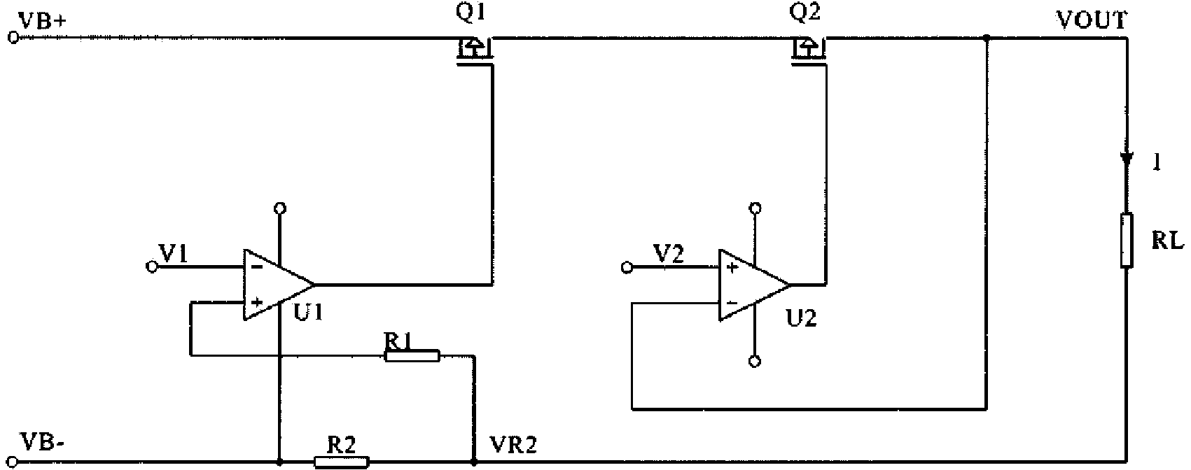
technical field [0001] The invention relates to a battery explosion-proof technology. Specifically, it is a battery explosion-proof circuit and a battery charging circuit. Background technique [0002] During the use of the battery, there are usually two situations that will cause the battery to explode: first, the gas inside the battery causes the battery to explode; second, the load current of the battery is too large to cause the battery to explode. For the first case, there are explosion-proof devices inside the battery, which can effectively avoid battery explosion; for the second case, it is necessary to avoid excessive load current to avoid battery explosion. [0003] Such as figure 1 As shown, the Chinese patent document CN202759272U discloses an explosion-proof battery current limiting circuit, which mainly includes: a first comparator U1 and a second comparator U2, a first electronic switch Q1 and a second electronic switch Q2, a protection resistor R1 and A cur...

Claims


Application Information

Patent Timeline
Patent Type & Authority Applications(China)
IPC IPC(8): H02H9/02H02H3/08H02J7/00
Inventor 宋小平马昂李凤石
Owner BEIJING TOCEL ELECTRONICS
Learn More