A temperature compensation circuit applied to laser driver

A technology of temperature compensation circuit and laser driver, which is applied in the direction of lasers, laser components, semiconductor lasers, etc., can solve the problems of small occupied area, troublesome application, large occupied area, etc., and achieve stable extinction ratio, save space, and convenient application Effect

Active Publication Date: 2016-08-24
JIAXING HEROIC ELECTRONICS TECH
View PDF3 Cites 0 Cited by
  • Summary
  • Abstract
  • Description
  • Claims
  • Application Information

AI Technical Summary

Problems solved by technology

In comparison, the former scheme will occupy a larger area and consume additional energy, and now the latter scheme is preferred
[0005] At present, most of the temperature compensation circuits used in laser drivers use off-chip resistors. This method not only occupies a large area, but also is troublesome to apply. It is necessary to select off-chip resistors according to the characteristics of semiconductor lasers and application needs. By adjusting the off-chip resistor To change the size and slope of the compensation current, it is urgent to design a circuit that occupies a small area and can flexibly adjust the compensation current

Method used


Image

  • A temperature compensation circuit applied to laser driver
  • A temperature compensation circuit applied to laser driver
  • A temperature compensation circuit applied to laser driver

Examples


Embodiment Construction

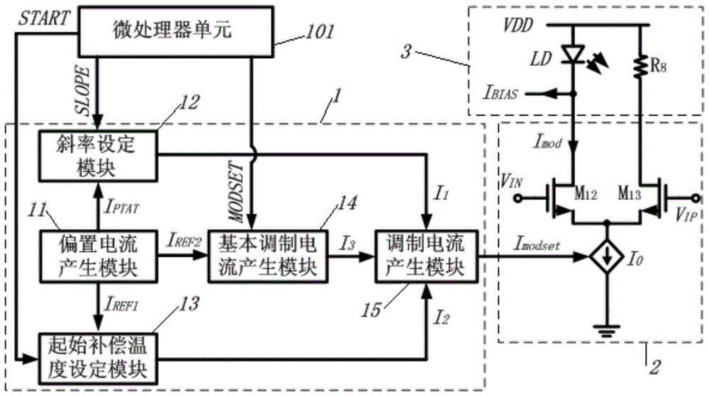
[0028] Such as figure 2 As shown, it is a block diagram of a specific embodiment of the present invention, including a bias current generation module 11, a slope setting module 12, an initial compensation temperature setting module 13, a basic modulation current generation module 14 and a modulation current generation module 15 , the external microprocessor 101 is externally connected.

[0029] The external microprocessor 101 inputs N-bit control words SLOPE, START and MODSET to the slope setting module 12, the initial compensation temperature setting module 13, and the basic modulation current generation module 14 respectively;

[0030] The bias current generation module 11 provides the bias current I that increases with temperature for the slope setting module 12, the initial compensation temperature setting module 13, and the basic modulation current generation module 14, respectively. PTAT , The temperature-independent bias current I REF1 , bias current I REF2 ;

[00...


PUM


Abstract

The invention discloses a temperature compensating circuit applied to a laser driver. The temperature compensating circuit comprises an external microprocessor, a bias current generation module, a slope setting module, a start compensation temperature setting module, a basic modulation current generation module and a modulation current generation module. Temperature compensation is carried out by means of a digital mode, the temperature compensation slope, the start compensation temperature and basic modulation currents can be flexibly adjusted by changing the input SLOPE value, the input START value and the input MODSET value according to temperature characteristics of a semiconductor laser unit and application demands, and therefore the extinction ratio of the semiconductor laser unit within a full-temperature range is kept stable. According to the compensation mode, an off-chip resistor does not need to be connected to the outside of the chip of the laser driver, space is saved, and the temperature compensating circuit is very convenient to apply.

Description

technical field [0001] The invention relates to a temperature compensation circuit, in particular to a temperature compensation circuit applied to a laser driver. Background technique [0002] In the optical communication system, the laser driver (LDD, Laser Diode Driver) and the semiconductor laser are important components of the optical transmitter. Semiconductor lasers are sensitive to temperature, and their output optical power varies greatly with temperature. figure 1 The optical power-current characteristic curves of semiconductor lasers at different temperatures are shown. As the temperature increases, the threshold current (Ith) of semiconductor lasers will increase significantly, and the electro-optical conversion efficiency of semiconductor lasers will also decrease significantly. For this characteristic of the semiconductor laser, the laser driver provides the required driving current for the semiconductor laser, and the driving current includes modulation curren...

Claims


Application Information

Patent Timeline
Patent Type & Authority Patents(China)
IPC IPC(8): H01S5/042
Inventor 黄立
Owner JIAXING HEROIC ELECTRONICS TECH
Why Eureka
Try Eureka