
Optical module current correction method, device and computer-readable storage medium

A storage medium and optical module technology, applied in the field of optical modules, can solve problems such as unqualified extinction ratio optical parameter indicators and large differences in laser working characteristics.

Active Publication Date: 2020-08-18
APAT OPTOELECTRONICS COMPONENTS
View PDF10 Cites 0 Cited by
  • Summary
  • Abstract
  • Description
  • Claims
  • Application Information

AI Technical Summary

Problems solved by technology

But in a certain high temperature range, using the bias current temperature lookup table to adjust the bias current will be quite different from the actual laser operating characteristics, making the optical parameter index of the extinction ratio unqualified

Method used


Image

  • Optical module current correction method, device and computer-readable storage medium
  • Optical module current correction method, device and computer-readable storage medium
  • Optical module current correction method, device and computer-readable storage medium

Examples


Embodiment Construction

[0041] It should be understood that the specific embodiments described here are only used to explain the present invention, not to limit the present invention.

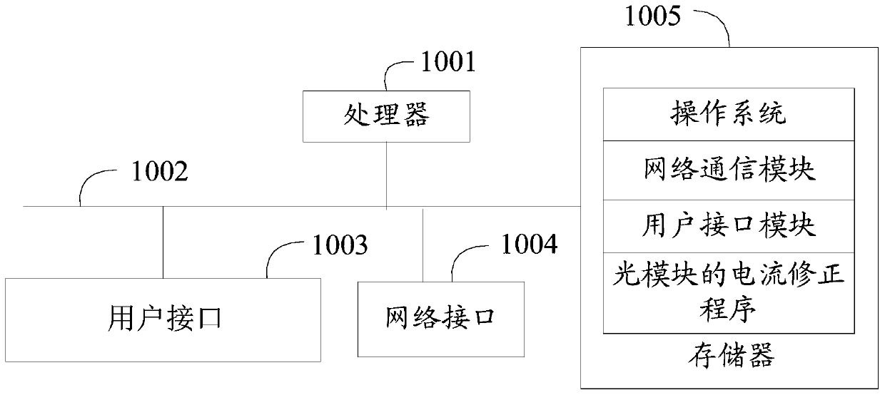
[0042] Such as figure 1 as shown, figure 1 It is a schematic diagram of the device structure of the hardware operating environment involved in the solution of the embodiment of the present invention.

[0043] The terminal in this embodiment of the present invention may be a PC, or a terminal device with a data processing function such as a smart phone, a tablet computer, or a portable computer.

[0044] Such as figure 1 As shown, the terminal may include: a processor 1001 , such as a CPU, a network interface 1004 , a user interface 1003 , a memory 1005 , and a communication bus 1002 . Wherein, the communication bus 1002 is used to realize connection and communication between these components. The user interface 1003 may include a display screen (Display), an input unit such as a keyboard (Keyboard), and the option...


PUM


Abstract

The invention discloses a current correction method of an optical module. The method includes: obtaining an original temperature lookup table of the optical module and a plurality of bias current adjustment values ​​within a preset temperature range; performing calculations according to the plurality of bias current adjustment values ​​and preset calculation formulas to obtain corresponding correction values, And correct the original temperature lookup table according to the correction value. The invention also discloses a current correction device of the optical module and a computer-readable storage medium. The present invention can implement and provide a method for correcting the temperature lookup table of the optical module, so as to ensure that the optical module is within a certain high temperature range, and also enable the optical module to load a suitable bias current on the laser, so that the extinction ratio of the optical module is stable within a certain range.

Description

technical field [0001] The present invention relates to the technical field of optical modules, in particular to a current correction method and device for an optical module and a computer-readable storage medium. Background technique [0002] The full name of the optical module is the optical transceiver module. It is the core device in optical communication and can complete the optical-electrical / electrical-optical conversion process of optical signals. It is composed of optoelectronic devices, functional circuits and optical interfaces. Among them, the optoelectronic devices Including receiving and transmitting two parts. Simply put, the receiving part is responsible for converting optical signals into electrical signals, and the transmitting part converts electrical signals into optical signals. During the optical-electrical / electrical-optical conversion process, as the temperature rises, the optical module needs to load the driving current to the internal laser through...

Claims


Application Information

Patent Timeline
Patent Type & Authority Patents(China)
IPC IPC(8): H01S5/042G06F30/20
CPCH01S5/042G06F30/20
Inventor 庄礼杰王侃王彦伟
Owner APAT OPTOELECTRONICS COMPONENTS
Learn More