
Differential Quasi-Yagi antenna with filtering function

A technology of Yagi antenna and function, applied in the field of differential quasi-yagi antenna, can solve the problems of large size and not compact structure of filter antenna, and achieve the effect of low loss, compact structure and good cross-polarization

Active Publication Date: 2014-07-30
ZHONGTIAN BROADBAND TECH +1
View PDF3 Cites 13 Cited by
  • Summary
  • Abstract
  • Description
  • Claims
  • Application Information

AI Technical Summary

Problems solved by technology

[0004] The technical problem to be solved by the present invention is to provide a differential quasi-Yagi antenna with integrated filtering function in view of the defects of the above-mentioned filter antenna in the prior art that the size is large and the structure is not compact enough

Method used


Image

  • Differential Quasi-Yagi antenna with filtering function
  • Differential Quasi-Yagi antenna with filtering function
  • Differential Quasi-Yagi antenna with filtering function

Examples


Embodiment Construction

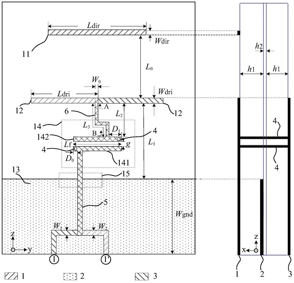
[0036] In order to have a clearer understanding of the technical features, purposes and effects of the present invention, the specific implementation manners of the present invention will now be described in detail with reference to the accompanying drawings.

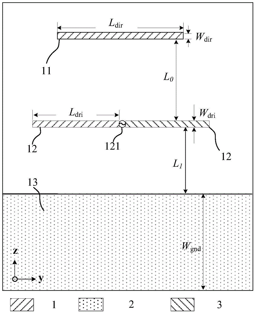
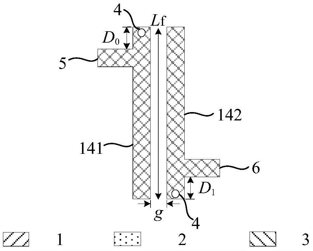
[0037] see figure 1 It is a structural schematic diagram of a differential quasi-Yagi antenna with integrated filtering function according to an embodiment of the present invention. The differential quasi-Yagi antenna with integrated filtering function in the embodiment of the present invention has a three-layer circuit structure. Specifically, the differential quasi-Yagi antenna with integrated filtering function in the embodiment of the present invention includes a substrate, the substrate includes an upper layer 1 and a lower layer 3 composed of a microwave dielectric substrate, and an intermediate layer 2 composed of a prepreg. Prepregs are used to bond two layers of microwave dielectric substrates. The dielectric...


PUM


Abstract

The invention discloses a differential Quasi-Yagi antenna with a filtering function. The differential Quasi-Yagi antenna with the filtering function comprises a substrate, wherein the substrate comprises an upper layer, a lower layer and a middle layer, the upper layer and the lower layer are both formed by microwave medium chips, and the middle layer is formed by prepregs. The differential Quasi-Yagi antenna with the filtering function further comprises a director (11), a radiating element (12), a reflector (13), a filter (14) and a transition structure (15). The differential Quasi-Yagi antenna with the filtering function has the advantages that the filtering function and the radiating function are integrated on the premise that the original size of the antenna is not increased, the structure is compact, cross polarization performance is high, and loss is low.

Description

technical field [0001] The invention relates to the field of antennas, in particular to a differential quasi-Yagi antenna with integrated filtering function. Background technique [0002] In most of today's RF front-end systems, the antenna and filter work as separate components. Due to the increasing demand for compact structure and low cost of passive components, integrating the filter into the antenna will be a very effective method, which not only realizes the miniaturization of microwave components but also improves the individual performance of microwave devices. Therefore, a compact filter antenna capable of both filtering and radiation performance is particularly important for today's radio frequency systems. [0003] The purpose of integrating the filter on the antenna is to make it have better frequency selectivity without changing the size of the antenna itself, which improves the integration of the system to a certain extent. Most of the existing filter antenn...

Claims


Application Information

Patent Timeline
Patent Type & Authority Applications(China)
IPC IPC(8): H01Q1/38H01Q1/48H01Q19/10H01Q1/00
Inventor 施金吴旭陈建新唐慧周立衡褚慧包志华
Owner ZHONGTIAN BROADBAND TECH
Learn More