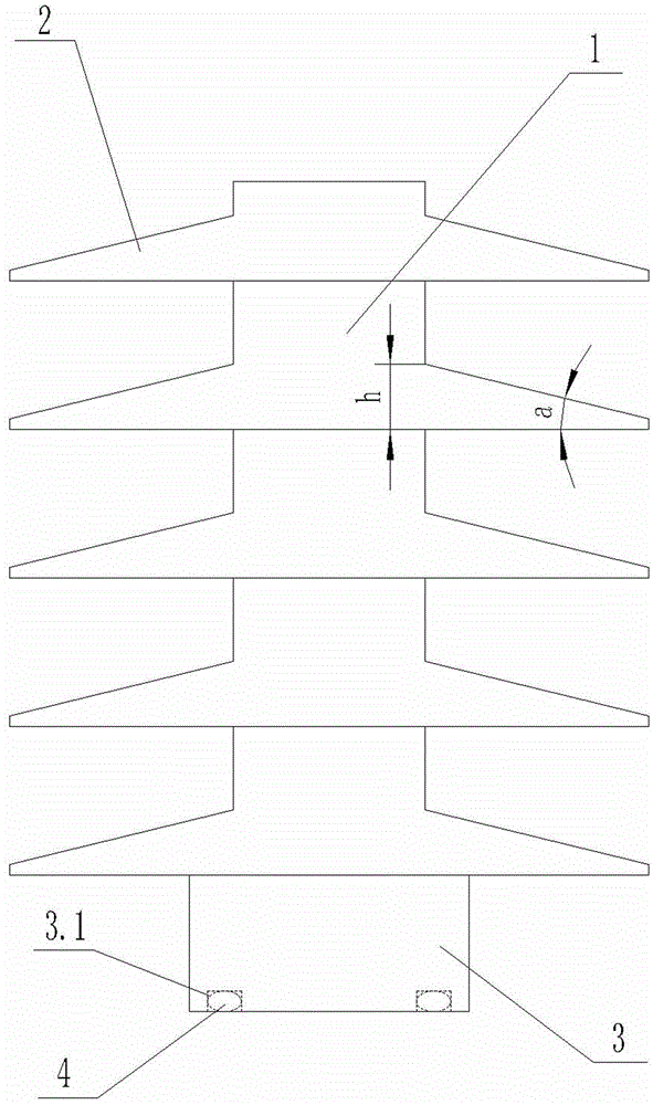
Insulation column for power equipment
A technology for power equipment and insulating columns, applied in the field of insulating columns, can solve problems such as creepage, pollution flashover, and poor effect
- Summary
- Abstract
- Description
- Claims
- Application Information
AI Technical Summary
Problems solved by technology
Method used
Image
Examples
Embodiment 1
[0029] Insulating coating composition formula is as follows in parts by weight:
[0030] Film-forming resin: 40 parts of brominated bisphenol A epoxy resin; modifier: 6 parts of methylphenyl silicone resin; filler: 20 parts of porcelain powder; diluent: 15 parts of xylene; curing agent: aliphatic amine 9 parts of primary amine; plasticizer: 10 parts of dibutyl phthalate.
[0031] The preparation method is as follows:
[0032] (1) Add the film-forming resin, modifier, diluent and plasticizer into the dispersion tank according to the proportion, stir and disperse evenly;
[0033] (2) Add the mixture and filler in step (1) into the paint grinding tank, stir and grind until the fineness is less than or equal to 45um;
[0034] (3) Fully stir the mixture in step (2) and curing agent to form an insulating coating.
[0035] The method of use is as follows:
[0036] The insulating coating is applied to the outer surface of the ceramic insulator by conventional methods such as spray...
Embodiment 2
[0039] Insulating coating composition formula is as follows in parts by weight:
[0040] Film-forming resin: 45 parts of brominated bisphenol A epoxy resin; modifier: 8 parts of methylphenyl silicone resin; filler: 15 parts of porcelain powder; diluent: 15 parts of xylene; curing agent: aliphatic amine 8 parts of primary amine; plasticizer: 9 parts of dibutyl phthalate.
[0041] The preparation method is as follows:
[0042] (1) Add the film-forming resin, modifier, diluent and plasticizer into the dispersion tank according to the proportion, stir and disperse evenly;
[0043] (2) Add the mixture and filler in step (1) into the paint grinding tank, stir and grind until the fineness is less than or equal to 45um;
[0044] (3) Fully stir the mixture in step (2) and curing agent to form an insulating coating.
[0045] The method of use is as follows:
[0046] The insulating coating is applied to the outer surface of the ceramic insulator by conventional methods such as sprayi...
Embodiment 3
[0049] Insulating coating composition formula is as follows in parts by weight:
[0050] Film-forming resin: 36 parts of brominated bisphenol A epoxy resin; modifier: 5 parts of methylphenyl silicone resin; filler: 25 parts of porcelain powder; diluent: 15 parts of xylene; curing agent: aliphatic amine 10 parts of primary amine; plasticizer: 9 parts of dibutyl phthalate.
[0051] The preparation method is as follows:
[0052] (1) Add the film-forming resin, modifier, diluent and plasticizer into the dispersion tank according to the proportion, stir and disperse evenly;
[0053] (2) Add the mixture and filler in step (1) into the paint grinding tank, stir and grind until the fineness is less than or equal to 45um;
[0054] (3) Fully stir the mixture in step (2) and curing agent to form an insulating coating.
[0055] The method of use is as follows:
[0056] The insulating coating is applied to the outer surface of the ceramic insulator by conventional methods such as spray...
PUM
 Abstract
Description
Claims
Application Information
 - R&D
- Intellectual Property
- Life Sciences
- Materials
- Tech Scout
- Unparalleled Data Quality
- Higher Quality Content
- 60% Fewer Hallucinations
Browse by: Latest US Patents, China's latest patents, Technical Efficacy Thesaurus, Application Domain, Technology Topic, Popular Technical Reports.
© 2025 PatSnap. All rights reserved.Legal|Privacy policy|Modern Slavery Act Transparency Statement|Sitemap|About US| Contact US: help@patsnap.com

