
Cutting insert and interchangeable cutting edge-type cutting tool

A technology of cutting inserts and indexing inserts, which is applied in the direction of milling cutting inserts, manufacturing tools, milling cutters, etc., can solve problems such as difficult to further increase feed rate and high feed processing, and achieve the goal of reducing cutting resistance and improving chip discharge Effect

Active Publication Date: 2014-07-23
MITSUBISHI MATERIALS CORP
View PDF10 Cites 23 Cited by
  • Summary
  • Abstract
  • Description
  • Claims
  • Application Information

AI Technical Summary

Problems solved by technology

Therefore, for example, the amount of feed per edge must be suppressed to prevent the thickness of chips from becoming too thick, and it is difficult to further increase the amount of feed to perform high-feed machining more efficiently.

Method used


Image

  • Cutting insert and interchangeable cutting edge-type cutting tool
  • Cutting insert and interchangeable cutting edge-type cutting tool
  • Cutting insert and interchangeable cutting edge-type cutting tool

Examples


Embodiment Construction

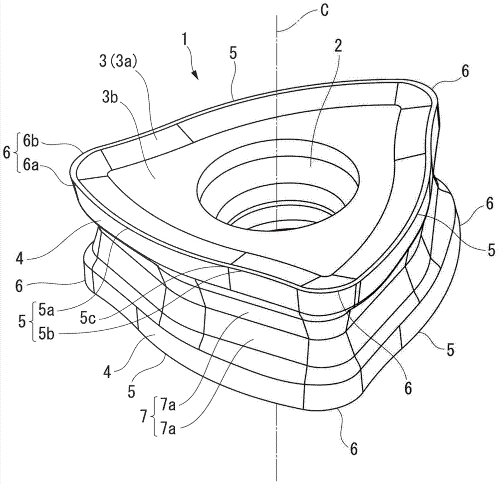
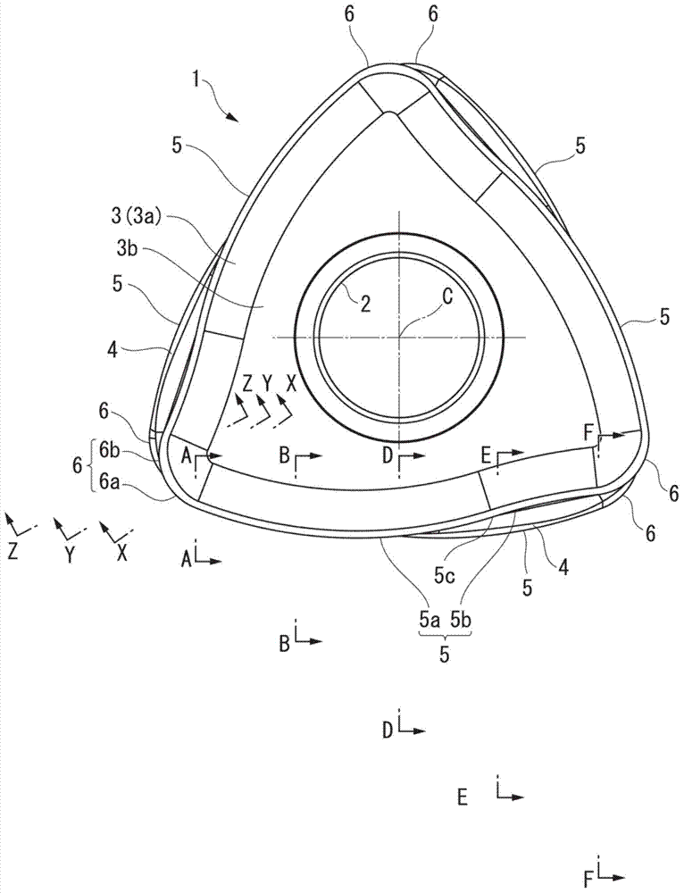
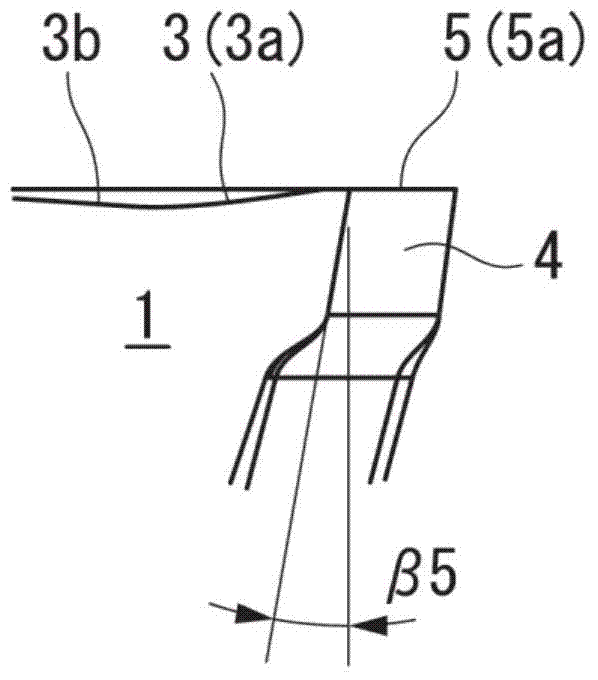
[0138] Figures 1 to 4C It is a figure which shows the 1st embodiment of the cutting insert of this invention, Figures 5 to 10C An indexable insert type end mill as a first embodiment of the indexable insert type cutting tool of the present invention equipped with the cutting insert of this embodiment is shown. In the cutting insert of this embodiment, the insert body 1 is formed in a polygonal plate shape by a hard material selected from cemented carbide, cermet, surface-coated cemented carbide, and surface-coated cermet. It is in the shape of a regular polygonal plate, and in this embodiment, it is in the shape of a regular triangular plate. Have a mounting hole 2 in the center of a pair of front and back polygonal faces (the first and second polygonal faces) of the blade body 1 in a regular triangle shape, and the mounting hole 2 is along the thickness direction of the blade body 1 ( figure 2 Orthogonal to the graph. Figure 3A ~ Figure 3E , Figure 4A ~ Figure 4C The...


PUM


Abstract

In the present invention, a cutting insert is provided with an insert body (1) having a polygonal plate shape. A rake face (3) is formed on the polygonal surface of the insert body (1) and flank faces (4) disposed at the periphery of the polygonal surface are formed on the lateral face of the insert body (1). At the intersecting ridge line between the rake face (3) and the flank faces (4), a main cutting blade (5) is formed at the side ridge of the polygonal surface. From among the corners of the polygonal surface, the main cutting blade (5) crosses and extends between two corners adjacent in the circumferential direction of the polygonal surface. Seen from the direction opposing the rake face (3), one edge (5a) of the main cutting blade (5) stretches to one of the two corners and has a protruding curved shape, and the other edge (5b) of the main cutting blade (5) stretches to the other of the two corners and has a recessed curved shape.

Description

technical field [0001] The present invention relates to a cutting insert detachably attached to an indexable insert cutting tool used in rotary cutting, and an indexable insert cutting tool to which the cutting insert is attached. [0002] This application is based on Japanese Patent Application No. 2011-271369 filed in Japan on December 12, 2011, Japanese Patent Application No. 2012-022187 filed in Japan on February 3, 2012, and Japanese Patent Application No. 2012-022187 filed in Japan on October 16, 2012. Patent application No. 2012-229181 claims priority and uses its content here. Background technique [0003] As an indexable insert type cutting tool, there is known a cutting tool for high-feed processing in which an end mill body as a tool body is fed out at a high feed rate to cut a workpiece. As cutting inserts mounted on such indexable insert type end mills for high-feed machining, for example, Patent Documents 1 and 2 propose negative cutting inserts that are appro...

Claims


Application Information

Patent Timeline
Patent Type & Authority Applications(China)
IPC IPC(8): B23C5/20B23C5/10
CPCB23C2200/286B23C5/109B23C5/2213B23C2200/0461B23C2200/0483B23C2200/125B23C2200/203B23C2210/168B23C2200/081B23C2200/161Y10T407/192Y10T407/235B23C5/202B23C5/205B23C2200/08B23C2210/50
Inventor 高桥秀史
Owner MITSUBISHI MATERIALS CORP
Learn More