
Design method for dreg slide plate curved surface of heading machine cutter head

A design method and ballast board technology, which are used in mining equipment, earth-moving drilling, tunnels, etc., can solve problems such as insufficient ballast removal, and achieve the effects of optimizing sliding trajectory, reducing vibration and improving strength.

Inactive Publication Date: 2014-04-30
DALIAN UNIV OF TECH
View PDF5 Cites 1 Cited by
  • Summary
  • Abstract
  • Description
  • Claims
  • Application Information

AI Technical Summary

Problems solved by technology

[0004] The problem to be solved by the present invention Aiming at the defects of the existing design technology of the cutterhead ballast slide plate, a design method for the curved surface of the cutterhead ballast slide plate of the roadheader is invented
The curved surface of the cutterhead ballast slide plate designed by this method is to change the ballast discharge trajectory of the rock ballast on the traditional ballast slide plate, so as to improve the problem that the ballast discharge cannot be fully discharged in some limit cases in the process of rock ballast discharge, and achieve the goal of rock ballast discharge process. Smooth and rapid features; at the same time, using the curved surface of the ballast plate to enhance the strength and rigidity of the cutterhead is of great significance in improving the working efficiency of the roadheader.

Method used


Image

  • Design method for dreg slide plate curved surface of heading machine cutter head
  • Design method for dreg slide plate curved surface of heading machine cutter head
  • Design method for dreg slide plate curved surface of heading machine cutter head

Examples


Embodiment Construction

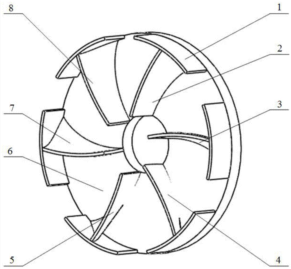
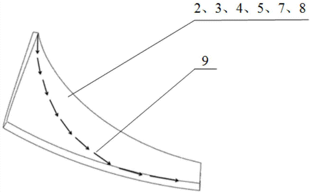
[0021] The specific implementation of the present invention will be described in detail in conjunction with the accompanying drawings and technical solutions. During the working process of the roadheader, the scraper is arranged around the cutterhead, and the rock crushed by the hob falls to the bottom of the cutterhead by its own weight. When the scraper passes through the bottom of the cutterhead, it will blow up this part of the rock After the ballast is blown up, the rock ballast will fall onto the ballast slide plate, and the rock ballast will gradually overcome the friction between the ballast slide plate and the ballast slide plate during the rotation of the cutter head, and then fall along the ballast slide plate to the belt conveyor for discharge.

[0022] The ballast discharge system of the roadheader has an important impact on the overall work efficiency. If the rock ballast cannot be discharged from the cutter head in time, the roadheader will not be able to continu...


PUM


Abstract

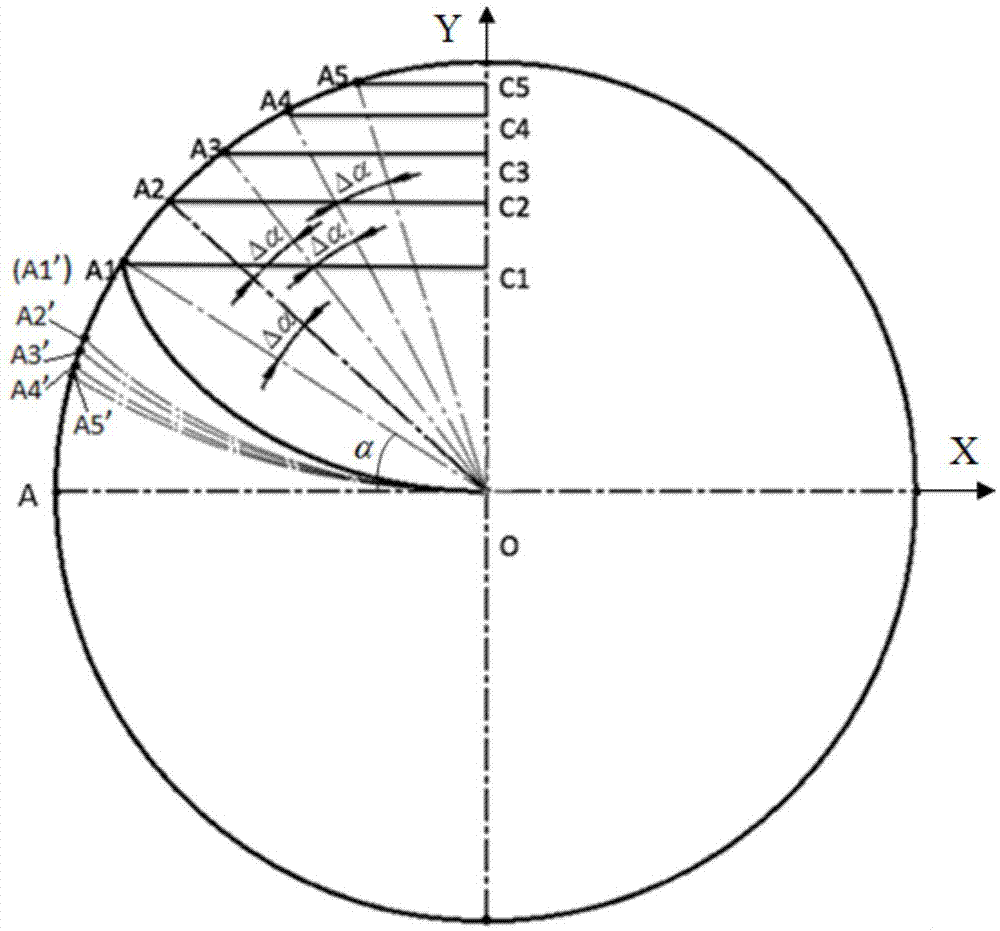
The invention relates to a design method for dreg slide plate curved surfaces of a heading machine cutter head, and belongs to the field of design methods for heading machine cutter head structures. In the surface design method, technical performance requirements for the overall heading machine cutter head, construction requirements and requirements for smooth dreg removal of the cutter head are taken into consideration, the dreg discharging track on conventional dreg slide plates is changed, and shapes of dreg slide plate curved surfaces of the cutter head are constructed according to the steepest descent curve. The design method includes respectively designing a first, a second, a third, a fourth, a fifth and a sixth dreg slide plate curved surfaces of the cutter head, and uniformly welding the designed dreg slide plate curved surfaces to a back panel of the cutter head and supporting plates on the periphery of the cutter head. In application of the cutter head dreg slide plate curved surfaces designed by the method, dregs slide smoothly and sequentially, the cutter head dreg discharging efficiency is increased, vibration and noises of the heading machine are reduced effectively by means of changing the dreg discharging track, and research cycle of the heading machine is shortened; therefore, heading service life of the heading machine cutter head is prolonged and economic loss caused in engineering is reduced.

Description

Technical field: [0001] The invention belongs to the field of the design method of the cutter head structure of the roadheader, in particular to a design method of the curved surface of the dregs slide plate of the roadheader cutter head. Background technique: [0002] As one of the most important components of the roadheader, the rationality of its design is closely related to the tunneling efficiency of the roadheader. The design method of the cutterhead structure includes the layout of the cutter, the design of the parameters of the disk body structure, the design of the dross scraper and the design of the dregs slide plate, etc. [0003] During the excavation process of the cutterhead by the roadheader, rock ballast accumulates at the bottom of the cutterhead under the action of gravity, and they are scraped into the cutterhead by the scraper plate and fall on the ballast slide plate. With the rotation of the cutter head, the rock ballast rolls down along the ballast sl...

Claims


Application Information

Patent Timeline
Patent Type & Authority Applications(China)
IPC IPC(8): E21D9/10
Inventor 霍军周吴瀚洋孙晓龙杨静
Owner DALIAN UNIV OF TECH
Learn More