
Three-phase fault-tolerant inverter circuit and control method thereof

An inverter circuit and circuit technology, applied in emergency protection circuit devices, electrical components, AC power input conversion to DC power output, etc., can solve the problems of high system cost, no fault tolerance, increased volume and weight, etc.

Inactive Publication Date: 2015-03-25
XIAN UNIV OF SCI & TECH
View PDF3 Cites 0 Cited by
  • Summary
  • Abstract
  • Description
  • Claims
  • Application Information

AI Technical Summary

Problems solved by technology

The voltage source inverter has been widely used due to its simple structure, flexible control and many other advantages. However, the power electronic device is the weak link most prone to failure, and its reliability problem has not been effectively solved.
The three-phase inverter usually adopts the standard three-phase bridge inverter structure, which does not have fault tolerance. In order to improve the reliability of the inverter, people usually design the inverter by derating the components or connecting redundant components in parallel. However, these two design methods will make the system cost too high and increase the volume and weight. In the application where the pursuit of low cost and the installation space are limited, the reliability of the inverter is still very prominent.

Method used


Image

  • Three-phase fault-tolerant inverter circuit and control method thereof
  • Three-phase fault-tolerant inverter circuit and control method thereof
  • Three-phase fault-tolerant inverter circuit and control method thereof

Examples


Embodiment Construction

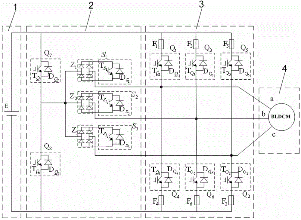
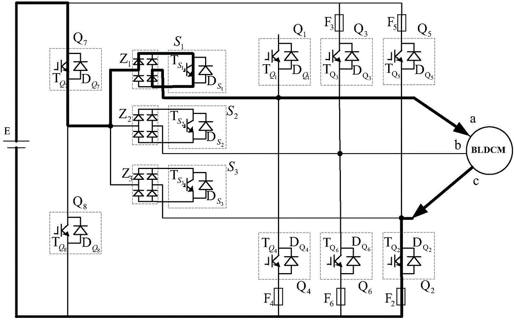
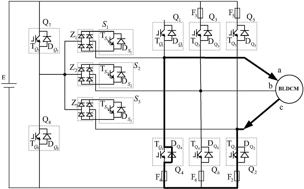
[0036] Such as figure 1 As shown, the three-phase fault-tolerant inverter circuit of the present invention includes a DC power supply 1 and an inverter bridge 3 for converting direct current into alternating current under the control of an external control circuit, and the inverter bridge 3 is formed by the first inverter bridge Arm, the second inverter bridge arm and the third inverter bridge arm, the upper bridge arm of the first inverter bridge arm is connected with the first upper bridge arm insulated gate bipolar transistor Q 1 , the lower bridge arm of the first inverter bridge arm is connected with a first lower bridge arm insulated gate bipolar transistor Q 4 , the connecting end of the upper bridge arm and the lower bridge arm of the first inverter bridge arm is the first output end of the inverter bridge 3, and the upper bridge arm of the second inverter bridge arm is connected with a second upper bridge Arm Insulated Gate Bipolar Transistor Q 3 , the lower bridge ...


PUM


Abstract

The invention discloses a three-phase fault-tolerant inverter circuit and a control method thereof. The three-phase fault-tolerant inverter circuit comprises a direct current power supply and an inverter bridge, the upper bridge arm of a first inverter bridge arm is connected with a high-speed fuse F1 while the lower bridge arm is connected with a high-speed fuse F4, the upper bridge arm of a second inverter bridge arm is connected with a high-speed fuse F3 while the lower bridge arm is connected with a high-speed fuse F6, and the upper bridge arm of a third inverter bridge arm is connected with a high-speed fuse F5 while the lower bridge arm is connected with a high-speed fuse F2; an auxiliary inverter circuit is connected between the direct current power supply and the inverter bridge and is composed of an auxiliary upper bridge arm insulated gate bipolar transistor Q7, an auxiliary lower bridge arm insulated gate bipolar transistor A8, an auxiliary first inverter bridge arm insulated gate bipolar transistor S1, an auxiliary second inverter bridge arm insulated gate bipolar transistor S2, an auxiliary third inverter bridge arm insulated gate bipolar transistor S3 and single-phase bridge rectifiers Z1, Z2 and Z3. The three-phase fault-tolerant inverter circuit and the control method thereof realize to isolate the fault of the bridge arm with short circuit or open circuit fault and have good fault-tolerant running function.

Description

technical field [0001] The invention belongs to the technical field of inverters, and in particular relates to a three-phase fault-tolerant inverter circuit and a control method thereof. Background technique [0002] Inverters are used to convert DC power into AC power. According to the nature of the DC side power supply, inverters are divided into current source inverters and voltage source inverters. The voltage source inverter has been widely used due to its simple structure, flexible control and many other advantages. However, the power electronic device is the weak link most prone to failure, and its reliability problem has not been effectively solved. The three-phase inverter usually adopts the standard three-phase bridge inverter structure, which does not have fault tolerance. In order to improve the reliability of the inverter, people usually design the inverter by derating the components or connecting redundant components in parallel. Inverter, but these two design...

Claims


Application Information

Patent Timeline
Patent Type & Authority Patents(China)
IPC IPC(8): H02M7/5387H02H7/122
Inventor 贺虎成
Owner XIAN UNIV OF SCI & TECH
Learn More