
Boost converter

A technology for converters and main switching tubes, which is applied in instruments, converting DC power input to DC power output, adjusting electrical variables, etc., and can solve the problems of large volume and weight of Boost converters, switching frequency limitations of switching tubes, etc.

Active Publication Date: 2014-07-23
SHENZHEN HUNTKEY ELECTRIC
View PDF5 Cites 6 Cited by
  • Summary
  • Abstract
  • Description
  • Claims
  • Application Information

AI Technical Summary

Problems solved by technology

[0008] The purpose of the embodiment of the present invention is to provide a Boost converter, aiming to solve the problem that the switching frequency of the switching tube is limited due to the switch-on loss and the turn-off loss of the Boost converter provided by the prior art due to the switching tube working in a hard switching state. , which makes the volume and weight of the Boost converter larger

Method used


Image

  • Boost converter
  • Boost converter
  • Boost converter

Examples


Embodiment Construction

[0030] In order to make the object, technical solution and advantages of the present invention clearer, the present invention will be further described in detail below in conjunction with the accompanying drawings and embodiments. It should be understood that the specific embodiments described here are only used to explain the present invention, not to limit the present invention.

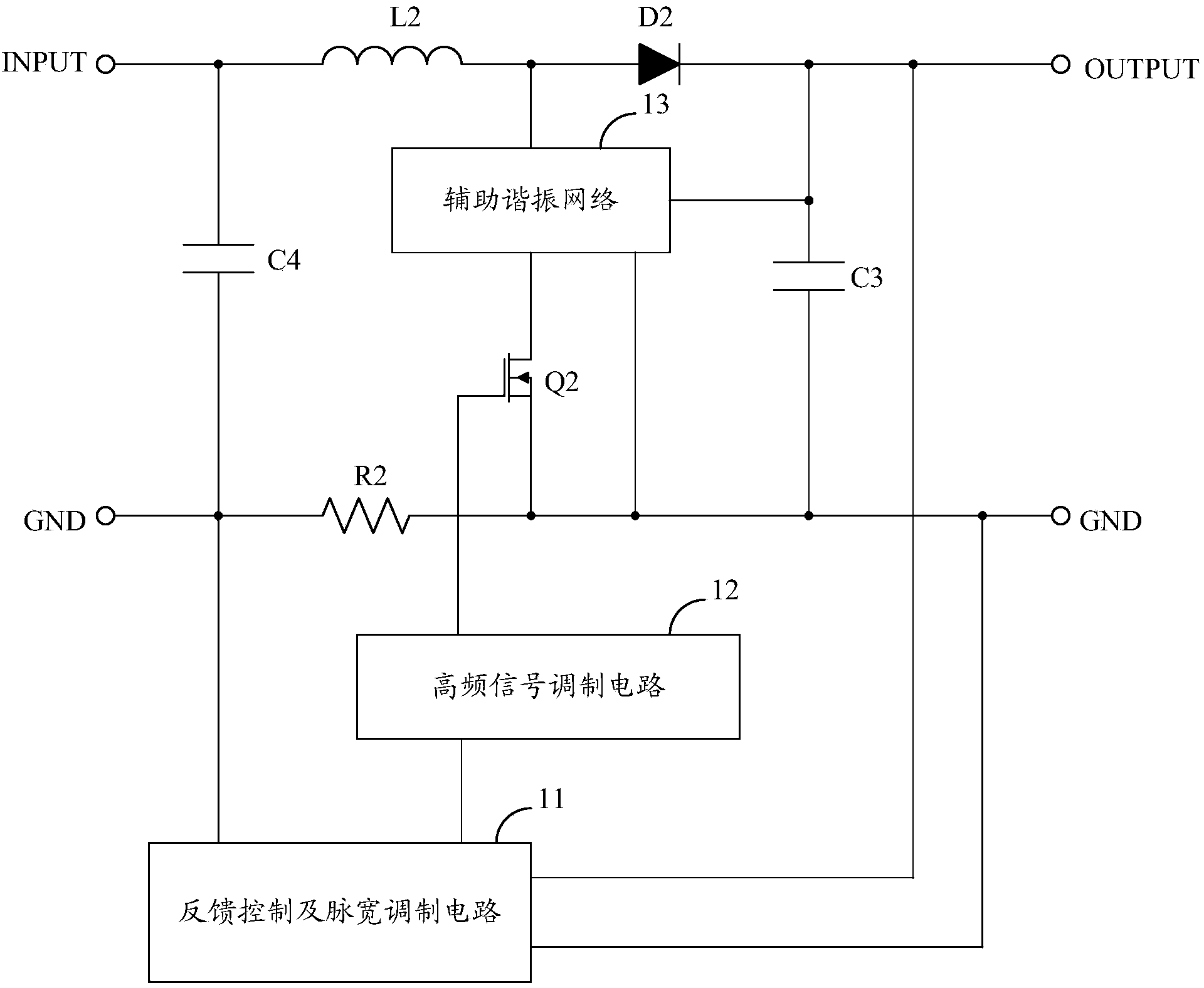
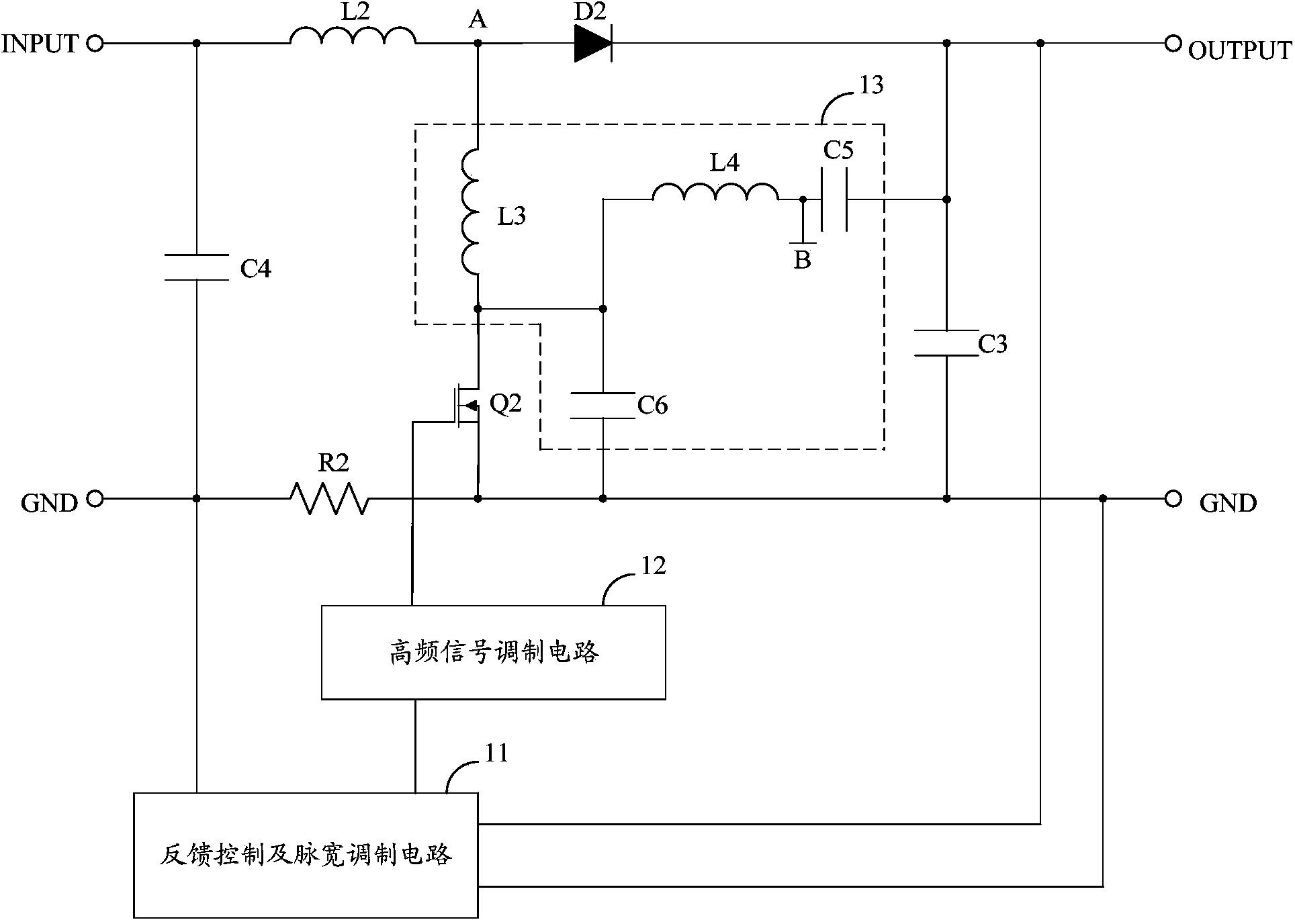
[0031] Aiming at the problems existing in the prior art, the present invention proposes a Boost converter. The Boost converter adds an auxiliary resonant network on the basis of the existing topological structure, and at the same time, adopts a combined control method of high-frequency signals and low-frequency signals for the main switching tube. Using the internal resonance of the auxiliary resonant network, at the moment of turning off the high-frequency signal, the voltage between the high-potential end and the low-potential end of the main switch rises from zero, and at the turn-on moment or t...


PUM


Abstract

The invention belongs to the field of switching power sources, and provides a Boost converter. The Boost converter is characterized in that an auxiliary resonance network is additionally arranged on the basis of an existing topological structure, and meanwhile a high-frequency signal and low-frequency signal combined control mode is adopted in a main switching pipe. Internal resonances of the auxiliary resonance network are adopted, at the moment when high-frequency signals are cut off, the voltage across the high-level end and the low-level end of the main switching pipe is increased from zero, and the zero-voltage shutoff of the main switching pipe is accordingly achieved; meanwhile, the voltage across the high-level end and the low-level end of the main switching pipe is decreased to zero at the startup moment or the shutoff period of the high-frequency signals, zero-voltage startup of the main switching pipe is accordingly achieved, and the main switching pipe can work in the high-frequency complete soft switching state or the high-frequency critically-complete soft switching state. In this way, magnetic elements and EMC filters can be small in design size by improving the switching frequency of the main switching pipe, and the size and the weight of the Boost converter are accordingly reduced.

Description

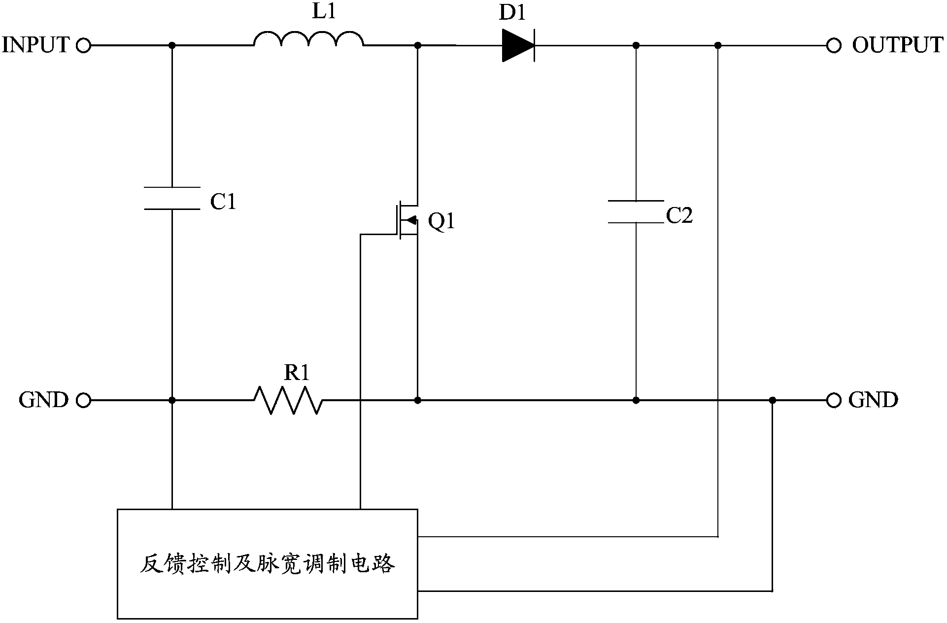
technical field [0001] The invention belongs to the field of switching power supplies, in particular to a Boost converter. Background technique [0002] A switching power supply is a device that adjusts the output voltage by controlling the switching duty cycle of a switching device, and is widely used in various electronic devices such as smart terminals. Boost converter is a common topology of switching power supply. [0003] Such as figure 1 A typical circuit of a Boost converter provided in the prior art is shown, wherein the feedback control and pulse width modulation circuit is used to output a pulse width modulation signal with a certain duty ratio to drive the switch tube Q1 to be turned on or off. The Boost converter can work in three states: the inductor L1 current continuous state, the inductor L1 current critical continuous state, and the inductor L1 current discontinuous state, in which the switch tube Q1 works as a hard switch with high voltage on and high cu...

Claims


Application Information

Patent Timeline
Patent Type & Authority Applications(China)
IPC IPC(8): H02M3/155
Inventor 吴智王卫江
Owner SHENZHEN HUNTKEY ELECTRIC
Learn More