
Device for catching and killing mosquitoes

A technology of electric extinguishing and sensor, which is applied to the device for capturing or killing insects, applications, animal husbandry, etc., can solve the problems of inability to effectively prevent the infestation of poisonous mosquitoes, environmental pollution, waste of funds, etc., and achieve comfortable and healthy home travel environmental effects

Inactive Publication Date: 2014-07-23
黄竹 +1
View PDF0 Cites 1 Cited by
  • Summary
  • Abstract
  • Description
  • Claims
  • Application Information

AI Technical Summary

Problems solved by technology

In living and residential areas, mosquitoes often hide in green areas or gutters, and bite visitors in the park during the day, and enter the house at night, making people uncomfortable. In order to deal with the harassment of poisonous mosquitoes, there are many kinds of lamp traps and mosquito killing devices in use today. However, they can only eliminate a small number of scattered flying mosquitoes, and cannot effectively block the infestation and harm of poisonous mosquitoes.
At present, the most commonly used method of killing mosquitoes in the sanitation department is to spray the green space with insecticides to eliminate hidden flying mosquitoes. Although this can temporarily kill mosquitoes, it will cause environmental pollution and waste of funds.

Method used


Image

  • Device for catching and killing mosquitoes
  • Device for catching and killing mosquitoes

Examples


Embodiment Construction

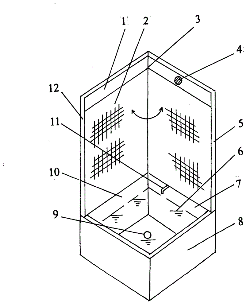
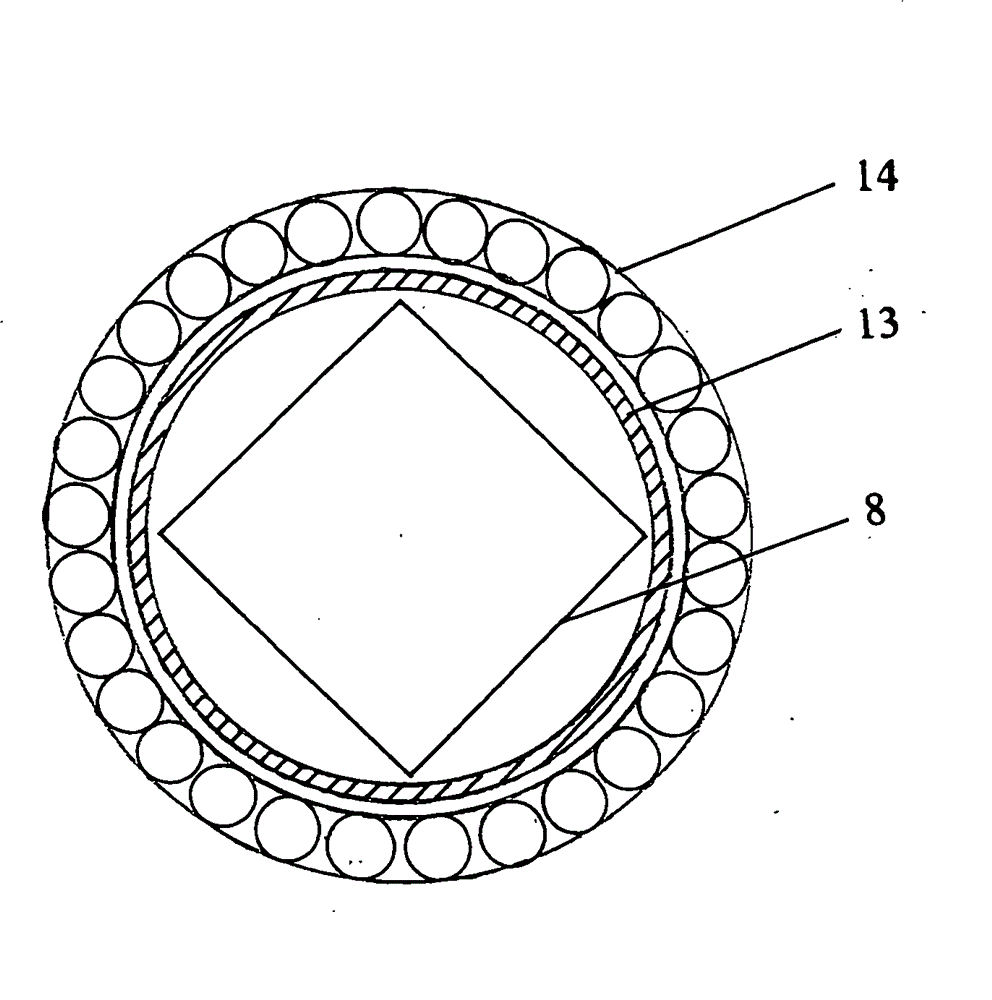
[0013] A mosquito swarm trapping device for electrically killing mating mosquito swarms, the structure of which is as follows figure 1 , figure 2 As shown, it includes a left wall 12, a solar panel 1, a right wall 5, a grid fan 2, a rotating shaft 3, an inductor 4, a water storage tank 8, a water inlet pipe 11, a drainage hole 9, a protective net 13 and a hedge 14, the The water storage tank 8 is square, the top of the water storage tank 8 is provided with a water inlet pipe 11, the bottom of the water storage tank 8 is provided with a drain hole 9, the water storage tank 8 contains a water body 6, and the left wall 12 and the right wall 5 are connected in a right-angle shape and a rotating shaft 3 is provided at the top of the corner. The rotating shaft 3 is connected to the grid fan 2. The grid fan 2 is made of fine stainless steel mesh. The rotating shaft 3 is driven by a motor controlled by an intelligent circuit. The left tank wall 10 of the water storage tank 8 is conn...


PUM


Abstract

The invention provides a device for catching and killing mosquitoes. The device is used for killing mating mosquitoes electrically. The device comprises a left wall, a solar cell panel, a right wall, a power grid fan, a rotating shaft, an inductor, a water storage tank, a water inlet pipe, a drain hole, a protective net and a hedge. The left wall and the right wall are connected to form a right-angle shape, the rotating shaft connected with the power grid fan is arranged at the position of an angular point, the left tank wall and the right tank wall of the water storage tank are connected with the left wall and the right wall respectively, the solar cell panel is arranged on the upper portion of the left wall, the inductor is arranged on the upper portion of the right wall, the water storage tank is provided with the water inlet pipe and the drain hole, and the safety protective net and the hedge landscape are arranged on the periphery of the water storage tank. At dawn and at dusk, when the inductor observes that the mating mosquitoes over the water storage tank enter the killing range of the power grid fan, the rotating shaft is driven by a motor to drive the power grid fan to rotate from the left wall to the right wall rapidly, and the mosquitoes are killed by electric shock of the power grid fan. The device can be laid in residential areas and scenic areas, is used for killing the mating mosquitoes electrically, prevents mosquito breeding from the source, and establish comfortable and healthy home and tourism environments.

Description

technical field [0001] The invention belongs to the technical field of mosquito breeding control, in particular to a mosquito swarm trapping device for electrically killing mating mosquito swarms. Background technique [0002] Mosquitoes bite people or animals, transmit various diseases, and cause great harm to human health. In living and residential areas, mosquitoes often hide in green areas or gutters, and bite visitors in the park during the day, and enter the house at night, making people uncomfortable. In order to deal with the harassment of poisonous mosquitoes, there are many kinds of lamp traps and mosquito killing devices in use today. But all can only eliminate a small number of scattered flying mosquitoes, and cannot effectively stop the infestation and harm of poisonous mosquitoes. At present, the most commonly used method of killing mosquitoes in sanitation and killing departments is to apply insecticides to spray green areas to eliminate hidden floating mosqu...

Claims


Application Information

Patent Timeline
IPC IPC(8): A01M1/22A01M1/24
Inventor 黄竹黄山
Owner 黄竹
Learn More