Motor vehicle drive train comprising a hydrodynamic retarder that can be disengaged, and control method therefor
A technology of hydraulic retarder and drive train, applied in the direction of hydraulic brake, hydraulic resistance brake, coupling and brake combination, etc., can solve the problems of high load, prolonged reaction time, time increase and so on
- Summary
- Abstract
- Description
- Claims
- Application Information
AI Technical Summary
Problems solved by technology
Method used
Image
Examples
Embodiment Construction
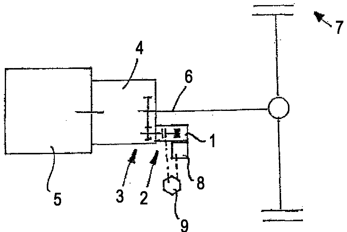
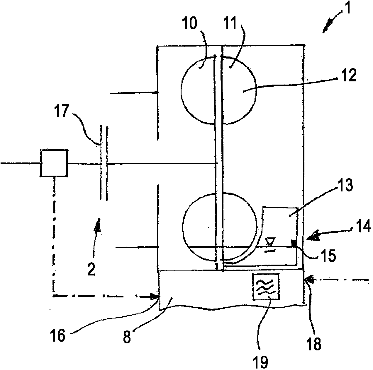
[0026] In these figures, a hydrodynamic retarder 1 can be seen, which is connected via a separating clutch 2 to a motor vehicle drive train 3 , here to an auxiliary output 3 in the form of a booster drive 4 . The transmission 4 is a stepping transmission, in particular an automatic transmission or an automated shifting transmission of a motor vehicle, which is driven on the input side by a motor, in particular an internal combustion engine 5, and which is driven on the output side via a transmission output shaft 6 The driving wheel 7 of motor car. The reduction gear 1 is provided with a control device 8 which at least controls the opening and closing of the separating clutch 2 or, when this is controlled by another device, prevents the closing of the separating clutch 2 . The control device 8 may or may itself be a disconnect clutch locking device, or may have access to such an in- figure 1 The decoupling clutch lock-up device represented by reference numeral 9.
[0027] exi...
PUM
 Abstract
Description
Claims
Application Information
 - Generate Ideas
- Intellectual Property
- Life Sciences
- Materials
- Tech Scout
- Unparalleled Data Quality
- Higher Quality Content
- 60% Fewer Hallucinations
Browse by: Latest US Patents, China's latest patents, Technical Efficacy Thesaurus, Application Domain, Technology Topic, Popular Technical Reports.
© 2025 PatSnap. All rights reserved.Legal|Privacy policy|Modern Slavery Act Transparency Statement|Sitemap|About US| Contact US: help@patsnap.com


