Liquid crystal display device

A liquid crystal display device and liquid crystal layer technology, applied in nonlinear optics, instruments, optics, etc., can solve problems such as prolonging production time, increasing costs, and long exposure time, so as to solve the afterimage problem, save manufacturing costs, and shorten production time Effect

Active Publication Date: 2016-08-17
KUSN INFOVISION OPTOELECTRONICS
View PDF4 Cites 0 Cited by
  • Summary
  • Abstract
  • Description
  • Claims
  • Application Information

AI Technical Summary

Problems solved by technology

However, this method is limited by the specific material chosen and is not suitable for cost savings
[0009] Second, by improving the level of technology, reduce the degree of asymmetry of the AC drive, and reduce the DC bias, but this method is limited by the process technology, and the DC bias cannot be fundamentally eliminated, and the afterimage problem cannot be fundamentally solved.
However, in order to reduce the load of the data line (data line) in this method, it is necessary to add a layer of OC protection layer (ie overcoat layer), specifically, as Figure 5 as shown, Figure 5 It is a schematic cross-sectional structure diagram of an array substrate of a liquid crystal display device after changing electrode positions. On a glass substrate 130, a gate 131, a gate insulating layer 132, an active layer 133, a source / drain layer 134, and a first insulating layer are sequentially formed. The protective layer 135, the OC protective layer 136, the first common electrode layer 137, the second insulating protective layer 138, the pixel electrode layer 139, and the first alignment layer (not shown in the figure), since the OC protective layer 136 needs to be added, not only an additional The cost of the photomask, and the exposure energy of the OC protective layer 136 is relatively high, and the exposure time is longer than that of the general photoresist, which will also prolong the production time and reduce the production capacity

Method used


Image

  • Liquid crystal display device
  • Liquid crystal display device
  • Liquid crystal display device

Examples


Embodiment Construction

[0032] In order to describe the technical content, structural features, achieved goals and effects of the present invention in detail, the following will be described in detail in conjunction with the embodiments and accompanying drawings.

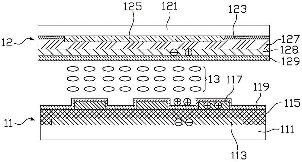
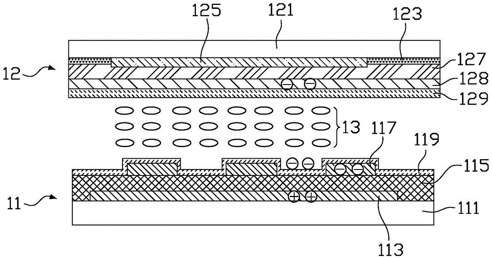
[0033] see Image 6 , Image 6 It is a schematic cross-sectional structure diagram of a liquid crystal display device according to the first embodiment of the present invention. The liquid crystal display device according to the first embodiment of the present invention includes an array substrate 31, a color filter substrate 32, and an array substrate 31 interposed between the array substrate 31 and the color filter substrate. 32 between the liquid crystal layer 33 . It should be noted that, for the sake of brevity, the figure only schematically shows the structure of one pixel area, and the drawing size and ratio of each component in the figure do not represent the actual size and ratio of the product.

[0034] The array substrate 31 i...


PUM


Abstract

A liquid crystal display device comprises an array substrate, a color film substrate, and a liquid crystal layer between the array substrate and the color film substrate. The array substrate comprises a first transparent base, pixel electrodes, an insulating protective layer, first common electrodes and a first alignment layer; the pixel electrodes, the insulating protective layer, the first common electrodes and the first alignment layer are formed on the first transparent base; the pixel electrodes and the first common electrodes are electrically insulated by the insulating protective layer; the first common electrodes are arranged above the pixel electrodes; the first alignment layer is formed on the insulating protective layer and covers the first common electrodes. The color film substrate comprises a second transparent base, a shade array and second common electrodes; the shade array and the second common electrodes are formed on the second transparent base. The insulating protective layer is provided with through holes corresponding to the shade array; the through holes penetrate the insulating protective layer and allow the pixel electrodes to be exposed; the first alignment layer fills the through holes and contacts with the pixel electrodes.

Description

technical field [0001] The invention relates to the technical field of liquid crystal display, in particular to a liquid crystal display device. Background technique [0002] Thin Film Transistor-Liquid Crystal Display (TFT-LCD) is widely used in the field of flat panel display because of its low radiation, thin thickness and low power consumption. Initially, most desktop TFT-LCDs used TN (Twisted Nematic, twisted nematic) mode. However, the pixel electrodes and common electrodes of TN-type liquid crystal displays are formed on the upper and lower substrates respectively, and the viewing angle range is relatively small. . [0003] In order to solve the viewing angle problem, the industry proposes liquid crystal displays using wide viewing angle technologies such as IPS (In-Plane Switching) mode and FFS (Fringe Field Switching, fringe field switching) mode. In addition, the Chinese patent application with the application number CN201310188430.6 (publication number CN1032680...

Claims


Application Information

Patent Timeline
Patent Type & Authority Patents(China)
IPC IPC(8): G02F1/1333G02F1/1337G02F1/1343
Inventor 钟德镇邵金凤戴文君
Owner KUSN INFOVISION OPTOELECTRONICS
Why Eureka
Try Eureka