
A sounding method using mimo arrays using transmitting subarrays

A technology of transmitting array and sub-array, applied in the field of array imaging, can solve the problems of low resolution of edge beam, increasing array size, and decreasing receiving aperture.

Inactive Publication Date: 2016-09-28
NORTHWESTERN POLYTECHNICAL UNIV
View PDF2 Cites 0 Cited by
  • Summary
  • Abstract
  • Description
  • Claims
  • Application Information

AI Technical Summary

Problems solved by technology

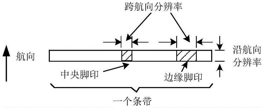
However, as the receive main lobe moves from the central beam to the edge beams, the receive aperture becomes progressively smaller and the beam footprint expands, i.e., the resolution of the edge beams is lower than that of the center beams (see image 3 )
To increase the aperture of the receiving linear array, the traditional method is to increase the size of the array or increase the frequency of the transmitted signal, which in turn faces the problems of AUV internal space limitations and increased absorption loss

Method used


Image

  • A sounding method using mimo arrays using transmitting subarrays
  • A sounding method using mimo arrays using transmitting subarrays
  • A sounding method using mimo arrays using transmitting subarrays

Examples


Embodiment Construction

[0023] The present invention will be further described below in conjunction with the accompanying drawings and embodiments, and the present invention includes but not limited to the following embodiments.

[0024] Main content of the present invention has:

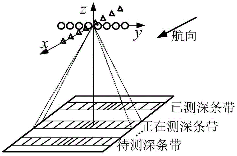
[0025] 1. Design a MIMO array that can be used for strip bathymetry. The array consists of two M0-element transmitting uniform linear arrays (ULA: Uniform Linear Array) and one N-element receiving ULA. Two transmitting ULAs form a pair of parallel and aligned transmitting sub-arrays, and the distance between them is equal to the number of receiving ULA array elements multiplied by the receiving array element spacing. Each transmitting ULA internally transmits coherent signals, and two transmitting ULA sub-arrays transmit mutually independent signals. At the transmit end, two transmit ULA sub-arrays transmit pulsed signals simultaneously and simultaneously "illuminate" a single strip beneath the AUV. At the receiving end...


PUM


Abstract

The present invention provides a MIMO array sounding method using transmitting sub-arrays. The two sub-arrays of the transmitting array are parallel and aligned with each other. The distance between the two sub-arrays is equal to the number of array elements of the receiving array multiplied by the array element spacing. The interior of the sub-array The transmission signals are coherent, the transmission signals between the sub-arrays are independent of each other, and the autocorrelation functions of the transmission signals of the two sub-arrays have the same main lobe and low side lobes, the two sub-arrays transmit pulse signals at the same time and illuminate a single strip at the same time , the receiving array collects echoes, and uses the transmission signals of the two transmitting sub-arrays to perform matched filtering processing on the echoes; multi-beam processing is performed on the output of the matched filtering to form multiple receiving beam footprints covering the bathymetric strip; the echo arrival is estimated Time delay, convert the time delay into the coordinates of the received beam footprint, that is, obtain the discrete depth of the strip. The present invention doubles the cross-course resolution of the multi-beam sounding system without increasing the physical size of the receiving linear array and increasing the frequency of the transmitted signal.

Description

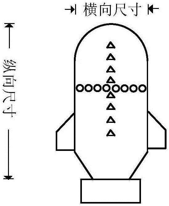
technical field [0001] The invention relates to an array imaging method. Background technique [0002] Multi-beam bathymetry systems installed on small underwater platforms (such as AUV and ROV) usually use Mills cross arrays, that is, mutually perpendicular transmitting linear arrays and receiving linear arrays (de Moustier C. State of the art inswath bathymetry survey systems . International Hydrographic Review, Monaco, 1988: 25-54. Wu Yingzi. Research on Terrain Tracking and Data Processing Technology of Multi-beam Bathymetry System. Doctoral Dissertation of Harbin Engineering University, 2002.). Take the cross array in Mill's cross array as an example, such as figure 1 As shown (where the triangle "Δ" represents the transmitting array element, and the circle "O" represents the receiving array element), in order not to destroy the line shape of the AUV, the physical size of the cross array must not exceed the horizontal and vertical dimensions of the AUV when deploying t...

Claims


Application Information

Patent Timeline
Patent Type & Authority Patents(China)
IPC IPC(8): G01S15/02
CPCG01S7/2813G01S7/282G01S7/42G01S13/08
Inventor 孙超刘雄厚卓颉
Owner NORTHWESTERN POLYTECHNICAL UNIV
Learn More