Method for measuring optical axis in aspheric surface detection by means of self-aligning plane mirror

A technology for measuring light and plane mirror, applied in the field of optical detection, can solve the problem of low measurement accuracy, and achieve the effect of high accuracy

Active Publication Date: 2014-07-16
CHANGCHUN INST OF OPTICS FINE MECHANICS & PHYSICS CHINESE ACAD OF SCI
View PDF7 Cites 23 Cited by
  • Summary
  • Abstract
  • Description
  • Claims
  • Application Information

AI Technical Summary

Problems solved by technology

[0003] In order to solve the problem of low measurement accuracy of the optical axis direction in the aspheric surface detection, the present invention proposes a method for measuring the optical axis based on the self-alignment detection of the plane mirror

Method used


Image

  • Method for measuring optical axis in aspheric surface detection by means of self-aligning plane mirror
  • Method for measuring optical axis in aspheric surface detection by means of self-aligning plane mirror

Examples


Embodiment

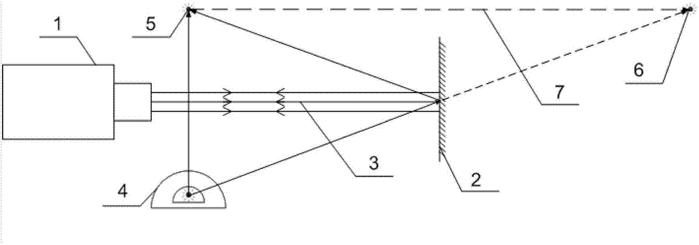
[0025] a. Place the plane mirror 2 close to the detected aspheric surface 10 (the farther away from the interferometer 1, the higher the measurement accuracy), and let the parallel light 3 emitted by the interferometer 1 shine on the plane mirror 2 Within the effective aperture; adjust the two angular directions of the yaw and pitch of the plane mirror 2, so that the interference fringes formed in the interferometer 1 are in the state of zero fringes; use the interferometer 1 to measure and analyze, and check the surface shape detection results Tilt amount (tilt item after zernike fitting), and continue to adjust the plane mirror 2 until the tilt is close to 0, and the adjustment is completed to realize the self-alignment of the plane mirror 2 to the interferometer;

[0026] b. Use the target ball of the laser tracker 4 to guide the laser light of the laser tracker 4 to the self-collimating plane mirror 2 and form a reflection, use the target ball to obtain the reflected laser ...


PUM


Abstract

The invention provides a method for measuring an optical axis in aspheric surface detection by means of a self-aligning plane mirror, and belongs to the technical field of optical detection. According to the method, the problem that orientation measurement accuracy of the optical axis is low in aspheric surface detection is solved. The method is used for adjusting relative positions and angles of the plane mirror and an interferometer, and enabling the direction of the plane mirror to be perpendicular to emergent light of the interferometer to generate interference fringes which are in a zero fringe state. A laser tracker is adopted to respectively measure a space coordinate of one point in space and a space coordinate of the mirror point, in the plane mirror, of the point, and the direction of the optical axis is obtained through the coordinates of the two points; a compensator is adjusted to be aligned to the interferometer, and an adjustment definition instrument is adopted to be aligned to the concave surface of the outer surface of a lens of the compensator; the laser tracker is used for measuring the position of a converge center of the adjustment definition instrument, namely, the position of the center of sphere of the outer surface of the lens, and obtaining a space coordinate of one point on the optical axis, and therefore the optical axis in a detection optical path is obtained with the combination of the optical axis direction obtained in the step 2; after the optical axis is obtained, mirror body characteristics are measured for positioning an aspheric surface mirror, and measurement and precision analysis can be carried out many times.

Description

technical field [0001] The invention relates to an optical axis measurement method in aspheric surface detection, in particular to an optical axis measurement method in long curvature radius aspheric surface detection, and belongs to the technical field of optical detection. Background technique [0002] The optical axis in the optical path of aspheric surface detection is the reference for the positioning of the detected component. Only by measuring the optical axis can the geometric quantities such as the eccentricity of the aspheric surface and the radius of curvature of the vertex be further measured or calculated. The measurement of the optical axis is the most critical link in the detection of positioning in the optical path, and its measurement accuracy determines the measurement accuracy of geometric quantities such as the eccentricity of the aspheric surface and the curvature radius of the vertex. The methods for measuring the optical axis in the detection of aspher...

Claims


Application Information

Patent Timeline
Patent Type & Authority Applications(China)
IPC IPC(8): G01M11/02
Inventor 陈新东李锐刚薛栋林郑立功
Owner CHANGCHUN INST OF OPTICS FINE MECHANICS & PHYSICS CHINESE ACAD OF SCI
Why Eureka
Try Eureka