
Cutting equipment and rotating worktable thereof

A technology of rotary table and rotary table, which is applied in the direction of workbench, manufacturing tools, etc., can solve the problems of complex structure, difficult maintenance, and low panel cutting accuracy, and achieve the effect of solving low positioning accuracy and ensuring horizontal stability

Active Publication Date: 2018-11-16
深圳市大族半导体装备科技有限公司
View PDF5 Cites 4 Cited by
  • Summary
  • Abstract
  • Description
  • Claims
  • Application Information

AI Technical Summary

Problems solved by technology

[0003] Based on this, it is necessary to provide a cutting device and its rotary table for the problems of low cutting precision, complex structure and difficult maintenance of panels

Method used


Image

  • Cutting equipment and rotating worktable thereof
  • Cutting equipment and rotating worktable thereof
  • Cutting equipment and rotating worktable thereof

Examples


Embodiment Construction

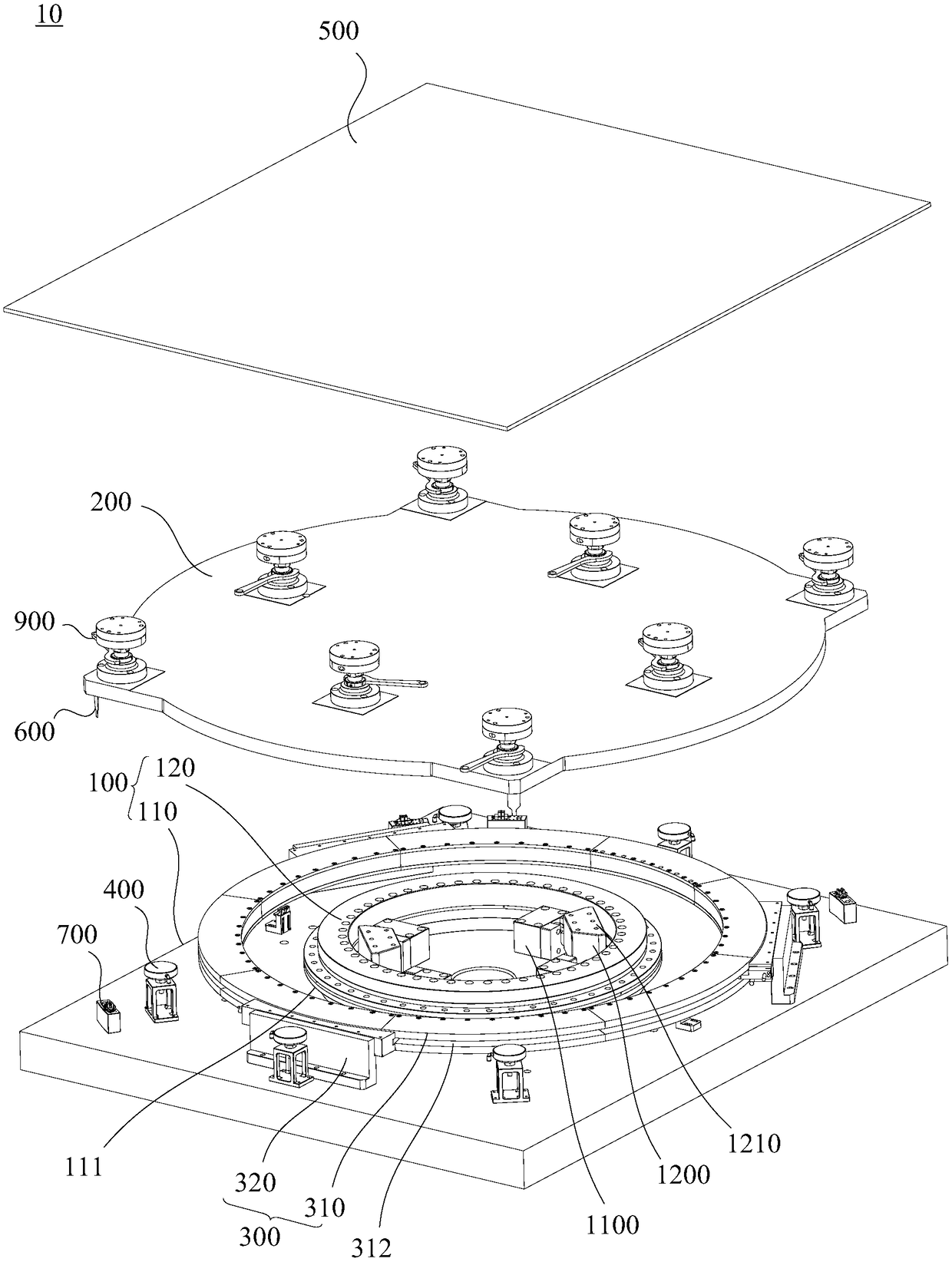
[0026] In order to facilitate the understanding of the present invention, the cutting device and its rotary table will be described more fully below with reference to the relevant drawings. A preferred embodiment of the cutting device and its rotary table is shown in the accompanying drawings. However, the cutting device and its rotary table can be implemented in many different forms and are not limited to the embodiments described herein. Rather, the purpose of providing these embodiments is to make the disclosure of the cutting device and its rotary table more thorough and comprehensive.

[0027] It should be noted that when an element is referred to as being “fixed” to another element, it can be directly on the other element or there can also be an intervening element. When an element is referred to as being "connected to" another element, it can be directly connected to the other element or intervening elements may also be present. The terms "vertical," "horizontal," "le...


PUM


Abstract

The invention relates to cutting equipment and a rotating worktable thereof. The rotating worktable comprises a base, a rotating table plate, a driving assembly, a plurality of floating assemblies, acarrying table, sensing pieces and photoelectric switches. The rotating table plate is rotatably connected to the base, the driving assembly is arranged on the base, and the power output end of the driving assembly is connected with the rotating table plate; the multiple floating assemblies are all arranged on the base, and each floating assembly is located between the rotating table plate and thebase, and used for supporting the rotating table plate in a floating mode; the carrying table is arranged on the side, away from the base, of the rotating table plate; the sensing pieces are arrangedon the rotating table plate; and the photoelectric switches are arranged on the base and correspond to the sensing pieces, and the photoelectric switches are in communication connection with the control end of the driving assembly and are used for sensing the sensing pieces and sending out sensing signals. The rotating worktable enables the rotating table plate to rotate to the predetermined angle position accurately and stably, and the problem of low positioning precision of a positioning mechanism is solved.

Description

technical field [0001] The invention relates to the technical field of panel cutting, in particular to a cutting device and a rotary table thereof. Background technique [0002] With the rapid development of the semiconductor manufacturing industry, panel cutting technology is becoming more and more diversified. Due to the gradual increase in cutting precision requirements for panels in the market, the traditional positioning mechanism for cutting panels has been unable to meet the needs of the market, that is, the precision of the positioning mechanism is low. In addition, the above-mentioned positioning mechanism has a complex structure and is difficult to maintain, which is not conducive to improving the production efficiency of panel cutting. Contents of the invention [0003] Based on this, it is necessary to provide a cutting device and a rotary table thereof for the problems of low panel cutting precision, complex structure and difficult maintenance. [0004] A ro...

Claims


Application Information

Patent Timeline
Patent Type & Authority Applications(China)
IPC IPC(8): B25H1/10B25H1/08
CPCB25H1/08B25H1/10
Inventor 吴林龙赖林松陈才伟周志伟马国东尹建刚高云峰
Owner 深圳市大族半导体装备科技有限公司
Learn More