
A fixture for ultrasonic perturbation electrolyte microporous electrolytic machining

A technology of electrolyte and jig, which is applied in the field of micro-electrolytic machining jigs, and can solve problems affecting the machining process, etc.

Inactive Publication Date: 2017-01-11
QINGDAO UNIV OF SCI & TECH
View PDF4 Cites 0 Cited by
  • Summary
  • Abstract
  • Description
  • Claims
  • Application Information

AI Technical Summary

Problems solved by technology

However, in order to achieve the purpose of disturbing the electrolyte and the effect of "cavitation" by ultrasonic waves, special fixtures must be used to allow the workpiece to be clamped conveniently and surrounded by the disturbed electrolyte, which really affects the processing process.

Method used


Image

  • A fixture for ultrasonic perturbation electrolyte microporous electrolytic machining
  • A fixture for ultrasonic perturbation electrolyte microporous electrolytic machining
  • A fixture for ultrasonic perturbation electrolyte microporous electrolytic machining

Examples


Embodiment Construction

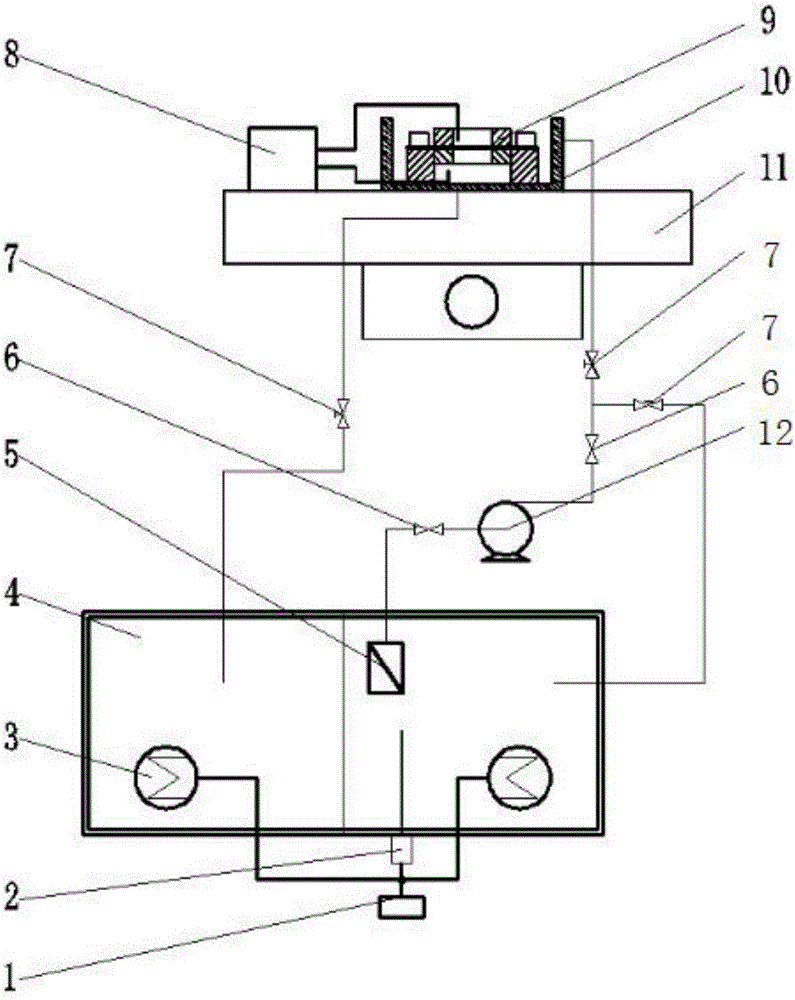
[0019] Such as figure 1 As shown, the ultrasonic disturbance electrolyte micro electrolytic processing system mainly consists of two parts, including temperature controller 1, thermocouple 2, heater 3, electrolyte tank and electrolyte 4, filter 5, check valve 6, ball valve 7. Electrolyte tank 10, multi-stage centrifugal pumps and pipelines constitute the electrolyte circulation system of the machine tool, supplying electrolyte for processing and discharging electrolytic products. The heater 3 is controlled by the thermocouple 2 and the temperature controller 1 to heat the electrolyte in the liquid tank 4 .

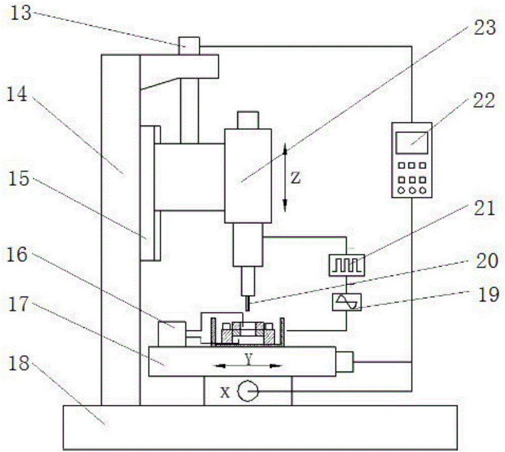
[0020] Such as figure 2 As shown, the machine tool column 14, the guide rail 15, and the marble base 18 in the whole machine tool for ultrasonically disturbing the electrolyte micro-electrolytic machining form the main body of the machine tool. The Z-axis stepping motor 13, the XY workbench 17, the controller 22, and the machine tool spindle 23 form the motion control s...


PUM


Abstract

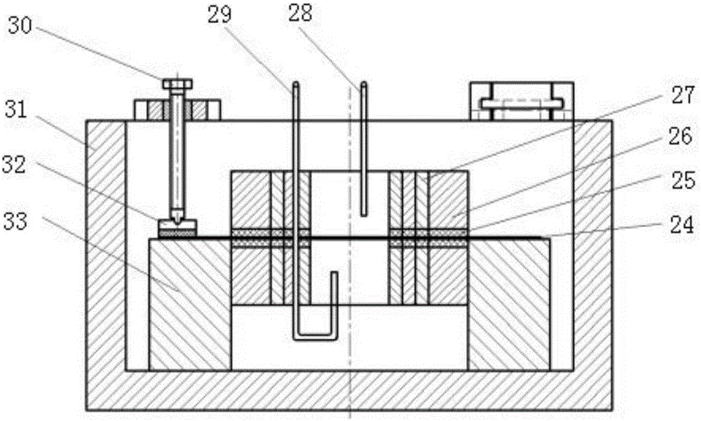
The invention relates to an electrolytic machining clamp, in particular to a clamp special for a machining area of an ultrasonic disturbance electrolyte micro-hole electrolytic machine tool. The clamp made by an insulating material is mounted on an XY workbench of the machine tool and ultrasonically transferred into an electrolyte tank, and electrolyte in the machining area is circulated through an inlet, an outlet and an electrolyte circulating system outside a clamp body. During electrolytic micro-hole machining, a workpiece is fixed on the clamp and immersed in the electrolyte completely, and ultrasonic waves act on the machining area to enable the electrolyte to generate high-frequency disturbance. By using the clamp, the workpiece can be enabled to be convenient in clamping, ultrasonic disturbance is centralized and stable and plays a role in cavitation in the process of machining, bubbles generated during electrolytic machining can be uniformly distributed, and flow field distribution is improved, so that electrolytic micro-hole machining accuracy is improved.

Description

technical field [0001] The invention relates to a micro-electrolytic machining fixture, which is a special fixture for ultrasonically disturbing the machining area of ​​a micro-electrolytic machining machine tool, and belongs to the technical field of electrolytic machining. Background technique [0002] Electrolytic machining is a special processing technology, which is a processing method that uses the principle of electrochemical anodic dissolution to remove materials. It has the outstanding advantages of fast processing speed, good surface quality, no loss of tools, no restrictions on material strength, toughness, hardness, etc., and no macro cutting force. It has been widely used in aerospace, weapons, automobiles, molds and other industries. [0003] With the continuous development of modern industry towards miniaturization and precision, more and more metal microstructures appear in the fields of microelectronics, aerospace, precision instruments and precision molds, ...

Claims


Application Information

Patent Timeline
Patent Type & Authority Patents(China)
IPC IPC(8): B23H11/00B23H3/00
Inventor 王蕾盖江宁王远哲王叶生
Owner QINGDAO UNIV OF SCI & TECH
Learn More