An inner locking push knife

An internal locking and tight technology, which is applied in the direction of broaching tools, broaching machines, metal processing equipment, etc., can solve the problem of large space occupation, and achieve the effect of small occupied space, long-lasting internal locking force and space saving

Active Publication Date: 2016-02-10
天津天海同步科技有限公司
View PDF7 Cites 0 Cited by
  • Summary
  • Abstract
  • Description
  • Claims
  • Application Information

AI Technical Summary

Problems solved by technology

[0003] Chinese patent CN2912873Y provides a special machine tool for horizontal push-cutting and processing of chain rail link nut faces, which discloses a push knife positioning structure commonly used in the prior art, that is, a clamping device for push knife is set at one end of the bed, and at the other end One end is provided with a table locking device, and the push knife is set between the clamping device and the locking device. This positioning structure can keep the push knife well positioned in the axial direction, but it takes up a lot of space and is not suitable for production. Spline gear products with small size and high precision requirements, such as gear sleeves in synchronizers

Method used


Image

  • An inner locking push knife
  • An inner locking push knife
  • An inner locking push knife

Examples


Embodiment Construction

[0023] Specific embodiments of the invention will be described in detail below in conjunction with the accompanying drawings.

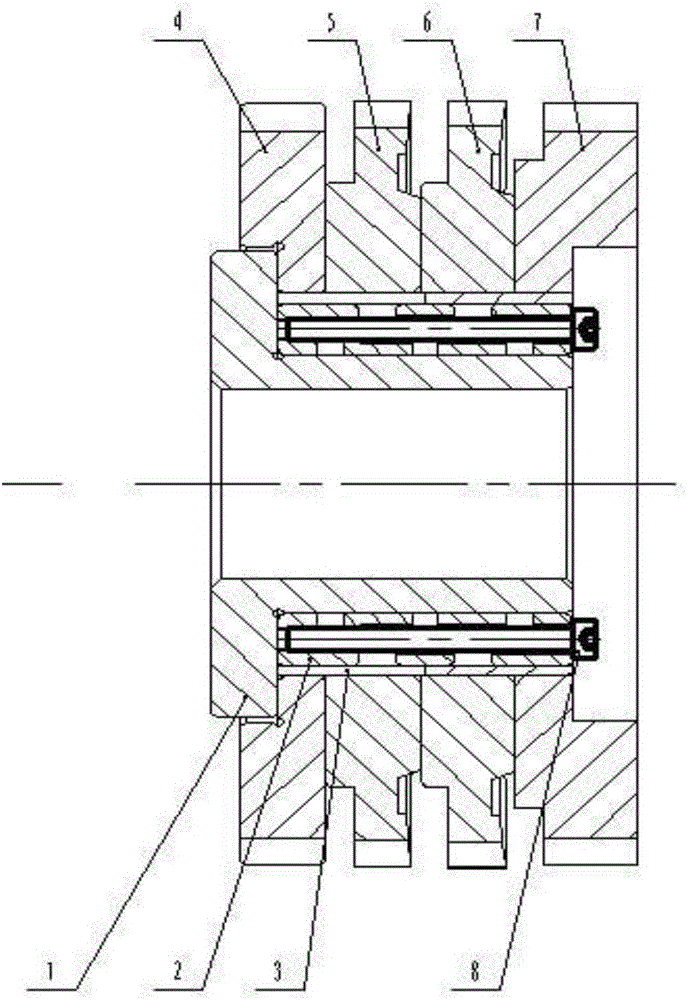
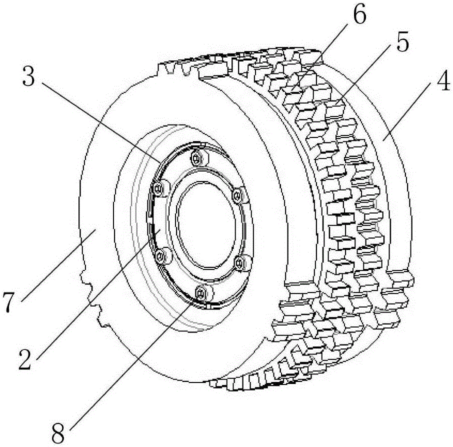
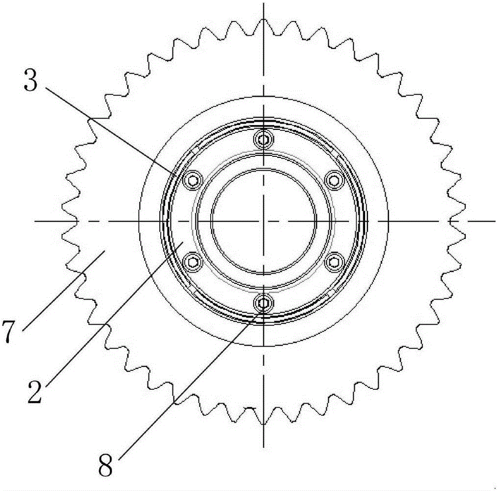
[0024] Such as figure 1 As shown, the inner locking push knife includes the expansion core 2, the expansion sleeve 3 and the locking bolt 8. The expansion sleeve 3 is set on the outside of the expansion core 2, and the outside of the expansion sleeve 3 is set with a rear guide from left to right. Part 4, spline push knife 5, rectangular spline 6 and front guide 7, the left end of the through hole at the central axis of the expansion core 2 is assembled on the support seat 1, and the end surface on the right side of the expansion core 2 is provided with an axial And the screw holes arranged in an annular array, the locking bolts 8 are screwed into the screw holes.

[0025] The support seat 1 is connected with the machine tool, and the locking bolt 8 is screwed in from the right side of the expansion core, the expansion core 2 continues to expand, the ...


PUM


Abstract

The invention provides an internally-locking-type push broach which comprises an expanding core, an expanding sleeve and locking bolts. The expanding sleeve sleeves on the outer side of the expanding core, a rear guide member, a spline push broach body, a rectangular spline and a front guide member are sequentially arranged on the outer side of the expanding sleeve from left to right in a sleeved manner, a through hole is arranged at a position of the central axis of the expanding core, a cylindrical supporting seat is arranged at the left end in the through hole in an inserted manner, multiple threaded holes in annular-array-type arrangement and parallel to the central axis of the expanding core are arranged on the right-side end face of the expanding core, and the locking bolts are arranged in the threaded holes. The push broach body, the guide members and the supporting seat are locked in an internally-locking manner through matched use of the expanding core and the expanding sleeve. Compared with conventional locking structures, an internally-locking structure of the internally-locking-type push broach is small in occupied space, and the internally-locking-type push broach is connected with a machine tool unilaterally, so that convenience is brought to mounting and demounting of workpieces, internally-locking force is lasting, and repeated locking is avoided.

Description

technical field [0001] The invention relates to a knife pushing device, in particular to a knife pushing device with an internal locking mechanism. Background technique [0002] Among the components of the automobile synchronizer, the axial movement of the tooth sleeve cooperates with the slider to push the synchronous ring and the inner cone ring tightly. It is used to place the slider and lock the synchronous ring and the inner cone ring during the synchronization process. The processing and grinding of the spline teeth in the gear sleeve are generally completed by push knives. Because the components of the synchronizer have high requirements for precision, it is required When the push knife advances in the axial direction, the force on each part of the inner ring surface of the gear sleeve is uniform, which puts forward high requirements for the positioning of the push knife on the machine tool. [0003] Chinese patent CN2912873Y provides a special machine tool for horiz...

Claims


Application Information

Patent Timeline
Patent Type & Authority Patents(China)
IPC IPC(8): B23D43/00
Inventor 胡占雄
Owner 天津天海同步科技有限公司
Why Eureka
Try Eureka