
Tubing installation tool for a peristaltic pump and methods of use

Inactive Publication Date: 2010-01-14
BLUE WHITE INDS
View PDF39 Cites 14 Cited by
  • Summary
  • Abstract
  • Description
  • Claims
  • Application Information

AI Technical Summary

Benefits of technology

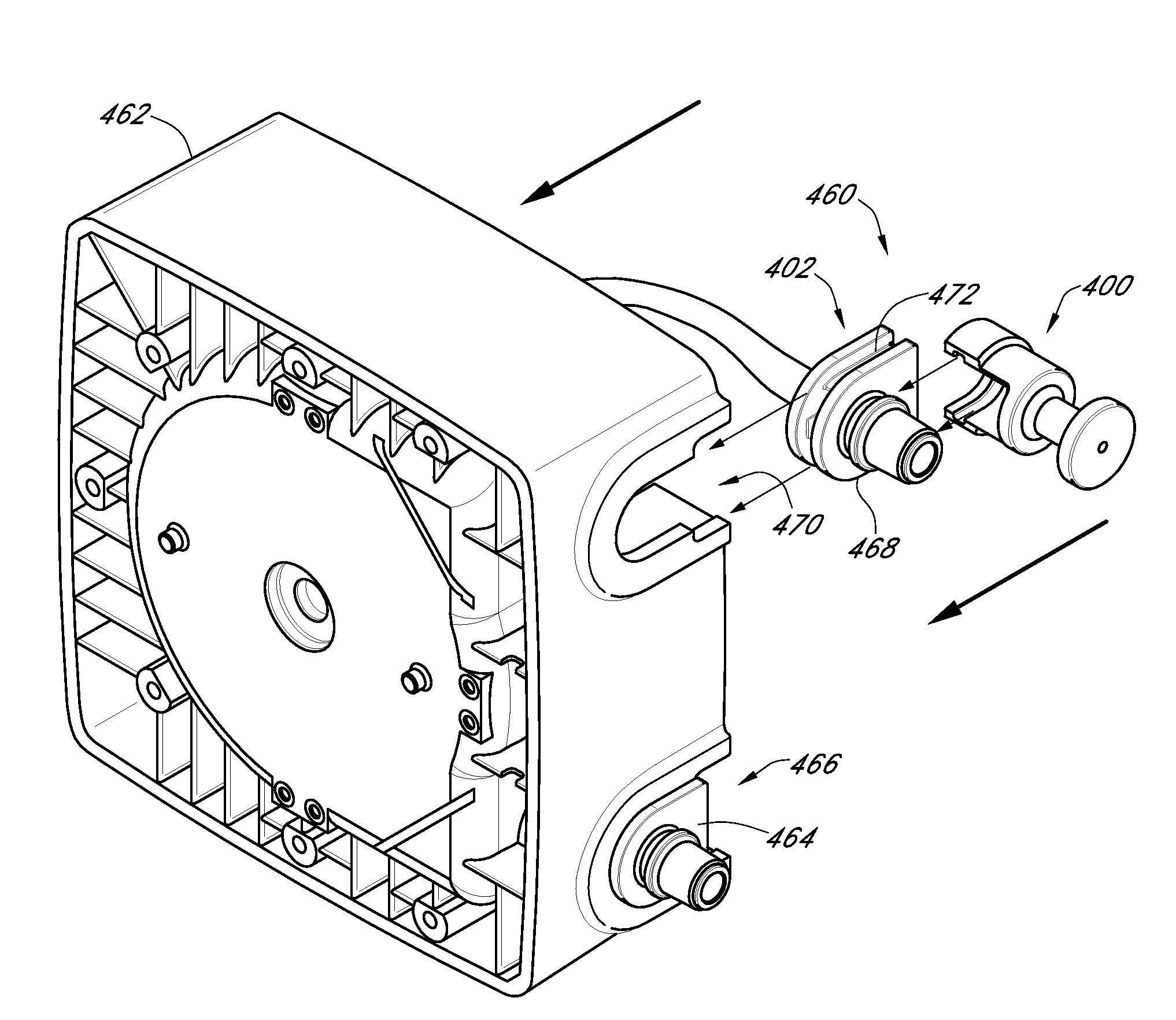
[0011]Embodiments of the tubing installation tool can greatly facilitate installation of a tubing assembly into a peristaltic pump. The installation tool can be selectively interconnectable with an end of the tubing assembly such that the tubing assembly can be stretched and manipulated by the operator during installation. For example, a first or inlet end of the tubing assembly can be attached to an inlet port of the pump, and with the installation tool interconnected with the second or outlet end of the tubing assembly, the tubing assembly can be guided into an internal cavity of the pump head and aligned with a roller(s) of a rotor of the pump. Subsequently, the tubing assembly can be pulled and positioned into the outlet port of the pump. In some embodiments, the tubing assembly can comprise an inlet connector and an outlet connector that can engage the respective inlet and outlet ports of the pump. In such embodiments, the installation tool can be extremely useful in pulling and positioning the outlet connector into the outlet port of the pump.
[0019]Various embodiments of a tubing installation tool are disclosed herein for facilitating installation of a tubing assembly in a peristaltic pump. For example, in an embodiment a tubing installation tool can be provided that comprises a handle portion and an engagement portion. The engagement portion can extend from the handle portion and comprise an interior cavity that defines a longitudinal axis. The interior cavity can be attachable with a connector of the tubing assembly. The interior cavity can comprise at least one slot formed therein for engaging a protrusion of the connector. Further, the engagement portion can comprise an opening formed along a side portion thereof that extends lengthwise relative to the longitudinal axis. The slot can be exposed through the opening of the engagement portion. The engagement portion can be coupled to the connector of the tubing assembly such that a protrusion of the connector is insertable into the slot by moving the connector in a direction generally perpendicular to the longitudinal axis of the engagement portion and into the opening of the engagement portion. Further, upon engagement of the protrusion with the slot and upon insertion of the connector into the cavity, the slot of the engagement portion can restrain axial movement of the connector relative to the tool.

Problems solved by technology

Over time, the high pressures at the pump outlet can wear on the tubing and result in the development of small pinholes in the tubing.
If unnoticed, the pinholes can grow and eventually result in failure of the tubing.
Ruptured tubing can lead to internal leakage and the cessation of proper function.
When the pump is used to move a corrosive chemical, such as chlorine, internal leakage can be particularly hazardous.
As the chemical comes into contact with the pump components, the pump may become irreparably damaged.
This is a serious shortcoming because the costs associated with replacement of the pump can be very substantial.
When tubing is replaced, the placement of the tubing underneath the rollers of the pump can be a very difficult task, especially in industrial applications.
This task is extremely difficult considering the narrow spacing between the rollers and the pump wall.
Indeed, it is exceedingly difficult to use the connectors, fittings, or ends of a tubing assembly to manipulate and bend the tubing assembly or interconnect the connectors with the respective inlet and outlet ports of the pump during installation.
Furthermore, rotation of the rotor during the maintenance mode of the peristaltic pump can be slower than rotation of the rotor during a normal operation mode of the peristaltic pump.
Moreover, rotation of the rotor during the maintenance mode of the peristaltic pump can be slower than rotation of the rotor during a normal operation mode of the peristaltic pump.

Method used


Image

  • Tubing installation tool for a peristaltic pump and methods of use
  • Tubing installation tool for a peristaltic pump and methods of use
  • Tubing installation tool for a peristaltic pump and methods of use

Examples


Embodiment Construction

[0030]While the present description sets forth specific details of various embodiments, it will be appreciated that the description is illustrative only and should not be construed in any way as limiting. Furthermore, various applications of such embodiments and modifications thereto, which may occur to those who are skilled in the art, are also encompassed by the general concepts described herein.

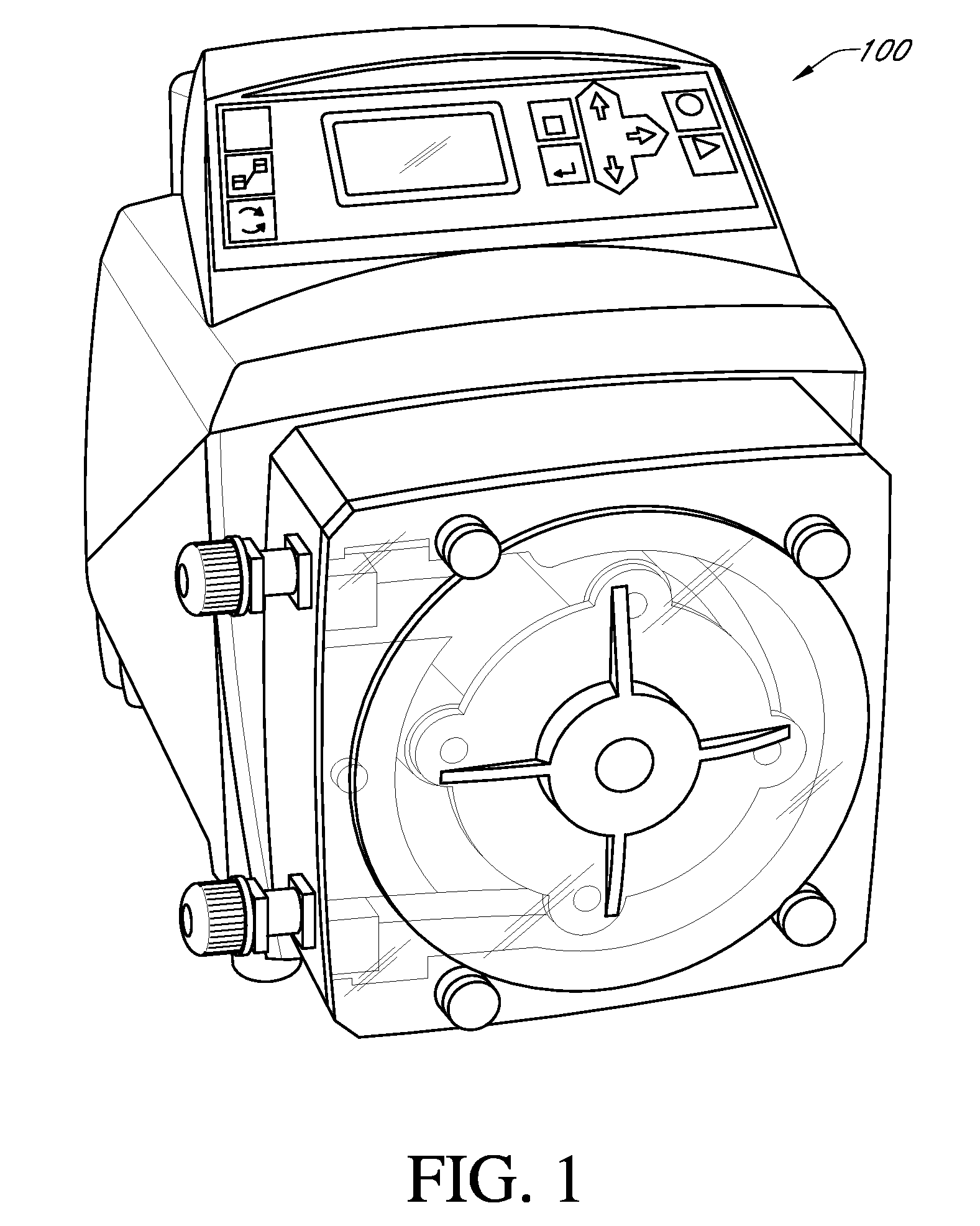
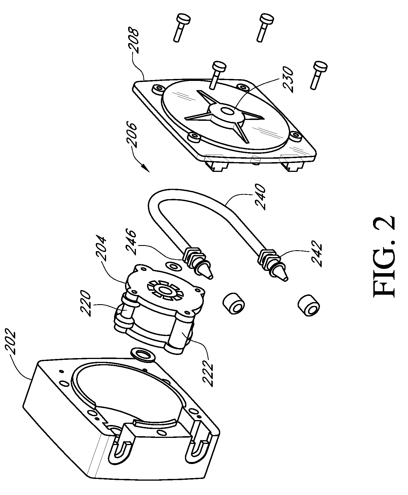
[0031]FIG. 1 is a perspective view of a peristaltic pump 100, according to an embodiment of the present inventions, and FIG. 2 is an exploded perspective view of components of a peristaltic pump, in accordance with an embodiment. As illustrated, the peristaltic pump can comprise a pump housing or head 202, a rotor 204 that rotates within a cavity of the pump head, a tube or tubing assembly 206, and a pump head cover 208 that encloses the rotor 204 and the tubing assembly 206 within the cavity of the pump head 202. The pump housing or head 202 can be formed such that the tubing assembly 206...


PUM

PropertyMeasurementUnit
Diameteraaaaaaaaaa
Widthaaaaaaaaaa
Circumferenceaaaaaaaaaa

Abstract

A peristaltic pump is provided that can comprise a safety switch in order to control an operational parameter of the pump in response to a state of the pump. Additionally, methods are provided for maintaining and replacing tubing of the pump. A tubing installation tool is also provided for handling industrial tubing during installation or removal of the tubing from a pump.

Description

CROSS-REFERENCE TO RELATED APPLICATIONS[0001]This application claims the benefit of U.S. Provisional Application No. 61 / 080,642, filed Jul. 14, 2008, the entirety of which is incorporated herein by reference.BACKGROUND[0002]1. Field of the Inventions[0003]The present inventions relate generally to peristaltic pumps. More particularly, the present inventions relate to a uniquely-configured peristaltic pump tubing installation tool and related methods of pump maintenance, such as replacing pump tubing.[0004]2. Description of the Related Art[0005]A peristaltic pump typically has one or more rollers that rotate and urge material through a flexible tubing, but may have other configurations. If a plurality of rollers is used, the rollers are spaced circumferentially evenly apart and are mounted on a rotating carrier that moves the rollers in a circle. A length of flexible tubing is placed between the roller(s) and a semi-circular wall. In medical applications, the tubing can be a relative...

Claims


Application Information

Patent Timeline
IPC IPC(8): B25B27/02
CPCB25B33/00Y10T29/49238Y10T29/49236Y10T29/4924Y10T29/53952
Inventor NGUYEN, JOHN
Owner BLUE WHITE INDS
Learn More