Structures for Exhaust Pipe Bending

A technology for exhaust pipes and support frames, which is applied in the field of pipe bending devices, can solve problems such as corrosion, metal fatigue, and environmental pollution, and achieve the effects of ensuring stable movement, ensuring force balance, and prolonging service life

Active Publication Date: 2016-05-04
CHENGDU HAILINGDA MACHINERY
View PDF9 Cites 0 Cited by
  • Summary
  • Abstract
  • Description
  • Claims
  • Application Information

AI Technical Summary

Problems solved by technology

In the production process of the exhaust pipe, simple pipe bending equipment is usually used for bending the exhaust pipe, and the pipe fittings are bent manually. Although this method is simple and easy, it not only increases the work intensity of the staff , There will be obvious wrinkles on the exhaust pipe after the bend, that is, the pipe fittings are partially bulged due to uneven force, and the local bulges of the pipe fittings are prone to metal fatigue. Corrosion, so that the tail gas emission of the loader is not up to standard, causing environmental pollution

Method used


Image

  • Structures for Exhaust Pipe Bending
  • Structures for Exhaust Pipe Bending
  • Structures for Exhaust Pipe Bending

Examples


Embodiment 1

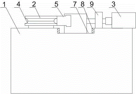
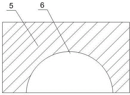
[0024] Such as Figure 1 to Figure 4 As shown, the structure of the present invention for bending exhaust pipes includes a support frame 1, a column 2 is installed on the support frame 1, an annular groove is opened on the column 2, and a hydraulic pressure is installed on the support frame 1. Cylinder 3, the output end of hydraulic cylinder 3 is connected with stopper 5, and described stopper 5 is facing the arc top of annular groove, and semicircle groove 6 is opened on described stopper 5, and the inner wall at both ends of semicircle groove 6 and A roller 10 is installed on the bottom of the groove, and the roller 10 is connected with the semicircular groove 6 through a rotating shaft 16; it also includes a sliding groove 7, which is arranged on the supporting frame 1, and travel switches 8 are installed at both ends of the sliding groove 7 , the travel switch 8 is connected with the control device of the hydraulic cylinder 3 through wires, and a damping structure is also ...

Embodiment 2

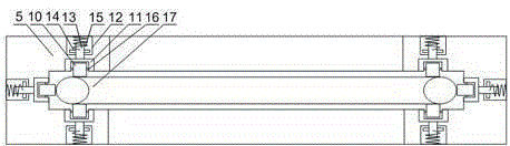
[0026] Such as figure 1 and image 3As shown, the present embodiment is based on Embodiment 1, and the damping structure includes a roller 10 support and a support cylinder 11, the support cylinder 11 is fixed in the semicircular groove 6, and the roller 10 is arranged on the roller 10 support through the rotating shaft 16. The bottom of the roller 10 bracket is provided with a support rod 13, the support rod 13 is installed in the support tube 11, the support rod 13 is provided with a limit block 14, and a torsion spring is installed between the limit block 14 and the bottom of the support tube 11 15. When the straight pipe piece 17 of the exhaust pipe is in contact with the two ends of the semicircular groove 6, under the propulsion of the hydraulic cylinder 3, the groove wall of the semicircular groove 6 and the roller 10 on the bottom of the groove begin to apply pressure to the straight pipe piece 17, and at the same time After the deformation of the pipe fitting 17, a ...

Embodiment 3

[0028] Such as image 3 As shown, in this embodiment, on the basis of Embodiment 1, the angle formed by the inner walls of the two ends of the semicircular groove 6 and the axis line of the roller 10 on the bottom of the groove is 60°. The distribution of the three rollers 10 on the semicircular groove 6 directly affects the stress of the straight pipe 17 of the exhaust pipe. The angle formed by the axis lines between the rollers 10 is 60°, so that the straight pipe 17 is placed in the semicircular groove 6. There are three evenly distributed stress points inside, and when the stopper 5 is pushed forward, the force balance of the straight pipe piece 17 is ensured, and indentation on the straight pipe piece 17 is avoided.


PUM


Abstract

The invention discloses a bending structure for an exhaust pipe. The bending structure for the exhaust pipe comprises a supporting frame. A stand column is installed on the supporting frame. An annular groove is formed in the stand column. A hydraulic cylinder is installed on the supporting frame. The output end of the hydraulic cylinder is connected with a stop block which is just opposite to the arc top of the annular groove. A semi-circular groove is formed in the stop block. Roller wheels are installed on the inner walls of the two ends of the semi-circular groove and the bottom of the semi-circular groove, and the roller wheels are connected with the semi-circular groove through a rotating shaft. With the arc top of the side, just opposite to the stop block, of the annular groove being the supporting point, the two ends of the semi-circular groove respectively apply action force on a straight pipe fitting so that the straight pipe fitting can start to bend and deform; the annular groove and the semi-circular groove are in cooperation so that the straight pipe fitting can gradually deform in a bent sealed space; as all parts of the straight pipe fitting in the bent sealed space are evenly stressed, the situation that the bent part of the straight pipe fitting protrudes locally is avoided, and the service life of the exhaust pipe is prolonged.

Description

technical field [0001] The invention relates to a pipe bending device, in particular to a structure for bending an exhaust pipe. Background technique [0002] The loader is mainly used for shoveling, loading, unloading, transporting bulk materials such as soil and stone, and can also perform light shoveling operations on rocks and hard soil. If you change to a different working device, it can also complete the work of bulldozing, lifting, loading and unloading other materials. In highway construction, it is mainly used for filling and excavation of roadbed engineering, aggregate and loading of asphalt and cement concrete yards. Because it has the advantages of fast operating speed, good maneuverability and light operation, it has become the main machine in earth and stone construction. [0003] When the loader is working, due to its heavy workload, compared with the angle direction of the exhaust pipe of cars and light family cars, it is generally backward and parallel to ...

Claims


Application Information

Patent Timeline
Patent Type & Authority Patents(China)
IPC IPC(8): B21D7/06
Inventor 陈志强
Owner CHENGDU HAILINGDA MACHINERY
Why Eureka
Try Eureka