
Battery winder

A battery roll and winding device technology, applied in the field of battery winding machines, can solve the problems of not meeting high efficiency, high quality production, affecting the quality of battery cores, and prone to deflection.

Active Publication Date: 2014-07-09
东莞市博拓锂电科技有限公司
View PDF5 Cites 25 Cited by
  • Summary
  • Abstract
  • Description
  • Claims
  • Application Information

AI Technical Summary

Problems solved by technology

[0003] However, there are still many defects in the existing lithium battery winding equipment. For example, the strip-shaped anode pole piece, cathode pole piece, left diaphragm and right diaphragm in the existing lithium battery winding equipment are all easy to move during the transmission process. The deflection occurs, which makes the anode pole piece, cathode pole piece, left diaphragm and right diaphragm deviate from the normal transmission position, resulting in extremely poor alignment of the edge of the wound battery core, which seriously affects the winding. Furthermore, the existing lithium battery winding equipment still has the disadvantages of complex structure, poor working stability, low winding precision, and long winding cycle, which affects the quality and production of electrical winding. Efficiency is far from meeting the needs of high-efficiency and high-quality production in modern manufacturing

Method used

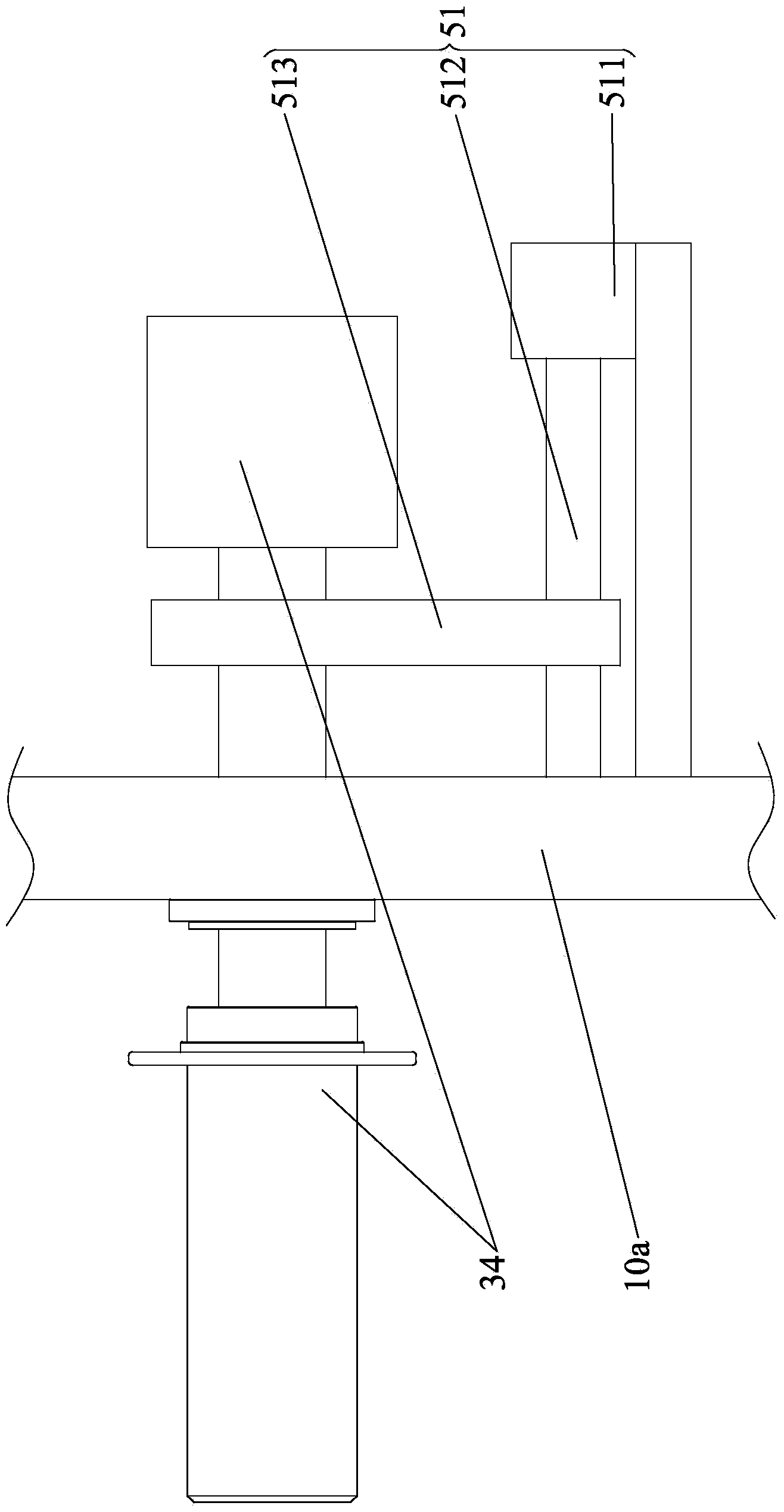
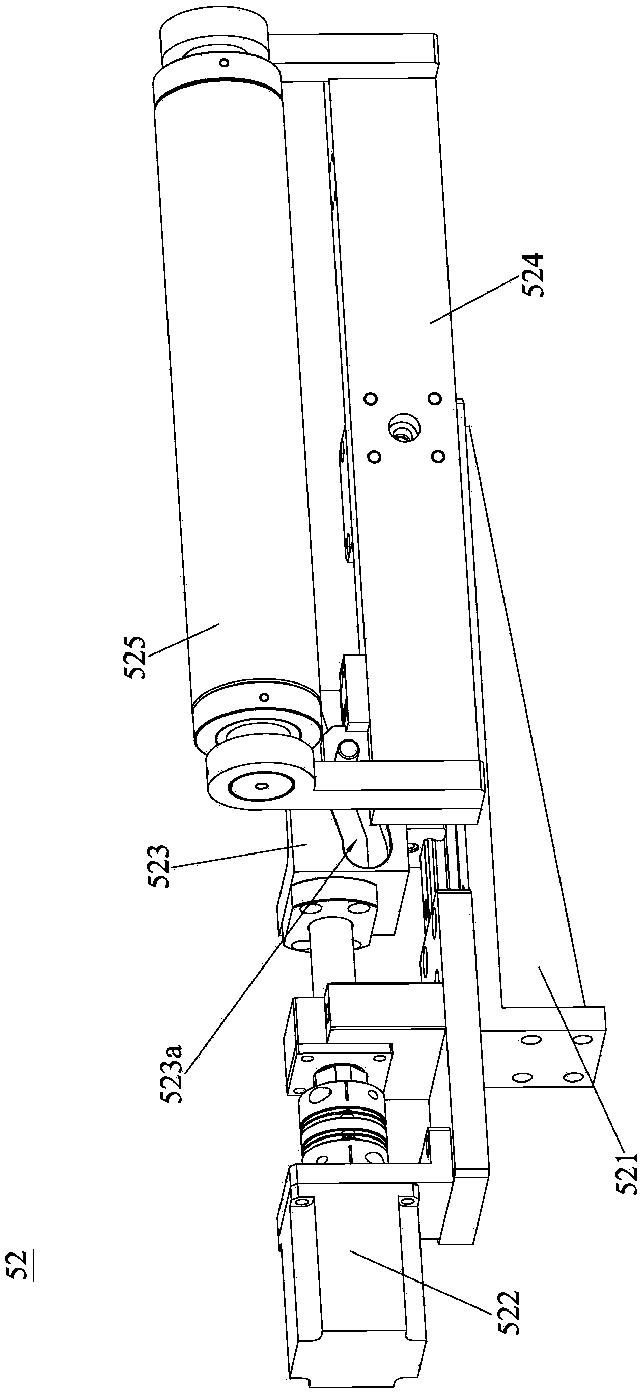

Image

  • Battery winder
  • Battery winder
  • Battery winder

Examples

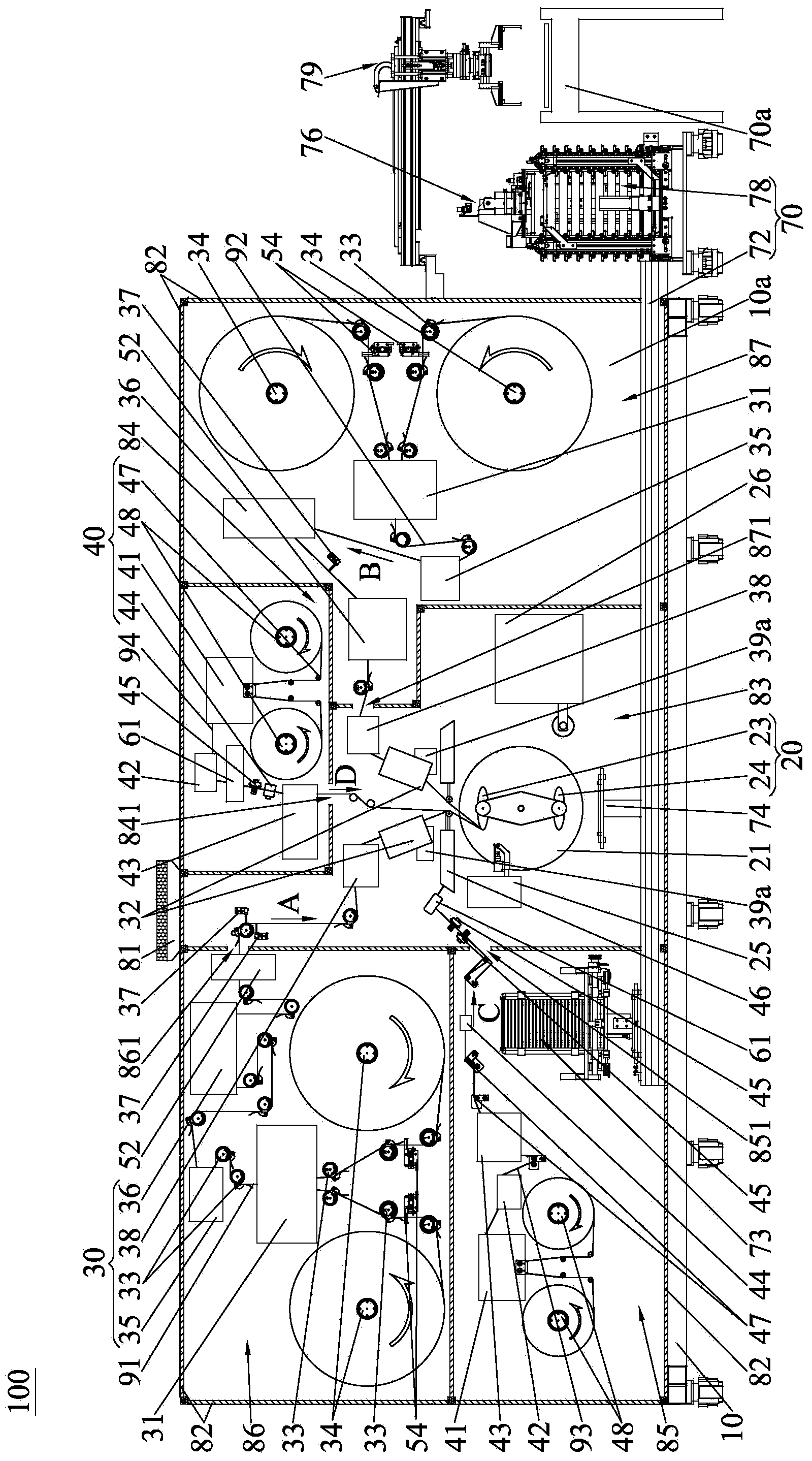

Embodiment Construction

[0026] In order to describe the technical content and structural features of the present invention in detail, further description will be given below in conjunction with the implementation and accompanying drawings.

[0027] see figure 1 , the battery winding machine 100 of the present invention is suitable for winding the strip-shaped anode pole piece 91, cathode pole piece 92, left diaphragm 93 and right diaphragm 94 to form a battery core (not shown in the figure), wherein, the present invention The battery winding machine 100 includes: a frame 10, a mounting substrate 10a, a winding device 20, a two-pole sheet conveying device 30 and two diaphragm conveying devices 40, the mounting substrate 10a is vertically arranged on the frame 10, the winding device 20, The two-pole sheet conveying device 30 and the two diaphragm conveying devices 40 are all arranged on the mounting substrate 10a. The mounting substrate 10a is preferably a whole plate with a non-splicing structure. The...


PUM


Abstract

The invention discloses a battery winder which comprises a rack, an installation base board, a winding device, a delivery mechanism of two pole pieces and a delivery mechanism of two membranes, wherein the installation base board is arranged on the rack along the vertical direction, the winding device is arranged on the installation base board, a positive pole piece and a negative pole piece are respectively delivered to the winding device by virtue of the delivery mechanism of the two pole piece, a left membrane and a right membrane are respectively delivered to the winding device by the delivery mechanism of the two membranes, the left membrane, the positive pole piece, the right membrane and the negative pole piece which are successively superposed are wound and formed, so as to obtain a cell, a pole piece edge detection device and a pole piece centring device are arranged on the pole piece delivery mechanism, the pole piece edge detection device is used for detecting the edge of the positive pole piece or the negative pole piece in real time, the pole piece centring device is used for rectifying a deviation for the positive pole piece or the negative pole piece in real time according to the detection data of the pole piece edge detection device, a membrane edge detection device and a membrane centring device are arranged on the membrane delivery mechanism, the membrane edge detection device is used for detecting the edge of the left membrane or the right membrane in real time, and the membrane centring device is used for rectifying a deviation for the left membrane or the right membrane in real time according to the detection data of the membrane edge detection device.

Description

technical field [0001] The invention relates to the field of battery production equipment, in particular to a battery winding machine. Background technique [0002] As we all know, in the lithium battery manufacturing industry, the lithium battery winding equipment is to wind the pole piece and the diaphragm together to form a battery cell, and then manufacture the finished lithium battery after a series of processes such as hot pressing, welding tabs, and liquid injection. Among them, cell winding is the core process in lithium battery manufacturing, and the quality of cell winding directly determines the performance of lithium batteries. [0003] However, there are still many defects in the existing lithium battery winding equipment. For example, the strip-shaped anode pole piece, cathode pole piece, left diaphragm and right diaphragm in the existing lithium battery winding equipment are all easy to move during the transmission process. The deflection occurs, which makes ...

Claims


Application Information

Patent Timeline
Patent Type & Authority Applications(China)
IPC IPC(8): H01M10/0587G01B21/00
CPCH01M10/0409H01M10/0587Y02E60/10Y02P70/50
Inventor 陈小明袁忠均王慧光
Owner 东莞市博拓锂电科技有限公司
Learn More