
Substrate etching method

A substrate and etching depth technology, applied in the field of microelectronics, can solve the problems of pollution particles, substrate contamination, and complicated etching steps, and achieve the effect of reducing manufacturing costs and simple etching steps

Active Publication Date: 2017-02-08
BEIJING NAURA MICROELECTRONICS EQUIP CO LTD
View PDF6 Cites 0 Cited by
  • Summary
  • Abstract
  • Description
  • Claims
  • Application Information

AI Technical Summary

Problems solved by technology

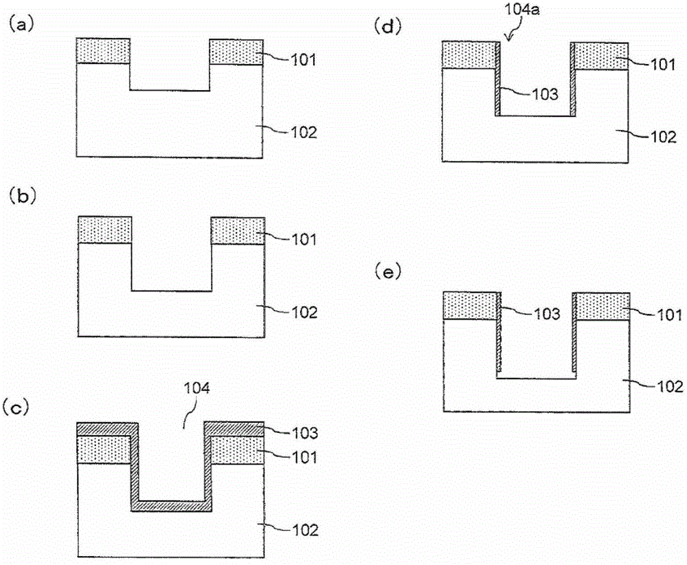
[0011] First, due to the complicated etching steps of the above-mentioned substrate etching method, it is easy to cause contamination particles to fall during the entire substrate etching process, thereby causing the substrate to be contaminated, thereby reducing the yield of the product
[0012] Second, since the protective film formation process of the above-mentioned substrate etching method uses sputtering to form a protective film on the substrate, this method requires special design of the etching equipment so that it has a sputtering function, resulting in equipment increase in manufacturing costs

Method used


Image

  • Substrate etching method
  • Substrate etching method
  • Substrate etching method

Examples


Embodiment Construction

[0044] In order for those skilled in the art to better understand the technical solution of the present invention, the substrate etching method provided by the present invention will be described in detail below in conjunction with the accompanying drawings.

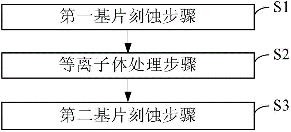
[0045] image 3 A flow chart of the substrate etching method provided by the present invention. see image 3 , the method is to divide the substrate etching process into two substrate etching steps, namely: the first substrate etching step and the second substrate etching step, and between the two, that is, after completing the first substrate etching step After the step, and before performing the second substrate etching step, a plasma treatment step is performed. Specifically, the following steps are included:

[0046] Step S1, the first substrate etching step. In step S1, an etching gas is fed into the reaction chamber, and an excitation power supply and a bias power supply are turned on, so as to etch the substra...


PUM


Abstract

Provided is a substrate etching method, comprising N times of substrate etching steps. In each time of substrate etching step, an etching gas is introduced into a reaction chamber, and an excitation power supply and a bias power supply are turned on to etch a substrate to a predetermined etching depth, where N is an integer greater than or equal to 2. It also comprises a plasma treatment step after the first time of substrate etching step and before the Nth time of substrate etching step. In the plasma treatment step, the introduction of the etching gas into the reaction chamber is stopped, simultaneously a treatment gas is introduced into the reaction chamber, and the bias power supply is turned off, the treatment gas being used for clearing away a part of reaction byproduct accumulated at the side wall of the substrate. The substrate etching method provided in the present invention not only can simplify the technological process, but also does not need to make any changes to an etching device on the premise of obtaining a substrate etching morphology with an ideal depth-to-width ratio, thereby being capable of reducing the manufacturing cost of devices.

Description

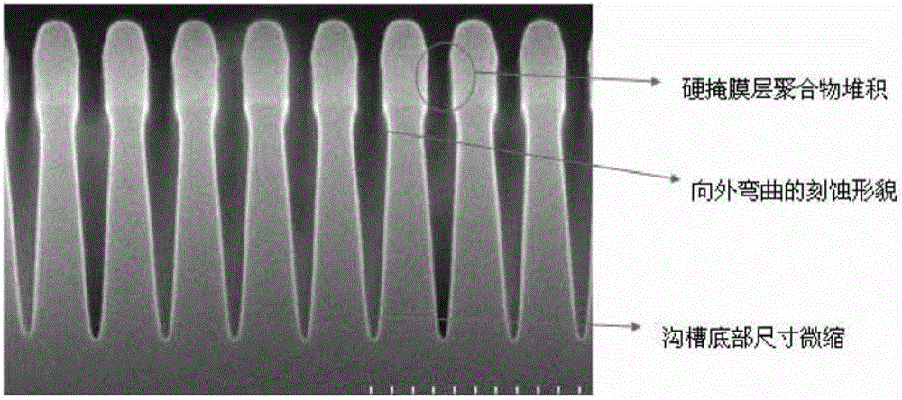
technical field [0001] The invention relates to the technical field of microelectronics, in particular to a substrate etching method. Background technique [0002] In recent years, with the increase in the integration of semiconductor devices, the size of individual components has gradually become smaller, which has higher requirements for the etching process of etching shallow trenches on the substrate, in order to obtain ideal deep trenches. wide-ratio substrate etch topography. [0003] At present, people usually use a continuous etching method to etch the substrate, that is, the total etching depth of the substrate is etched in one step, and by adjusting the excitation power and the flow rate of etching gas (such as HeO) and other parameters to improve the smoothness of the sidewall topography of the substrate trench. However, when the substrate etching process is performed, especially when the process node is 32nm and below, the reaction by-products generated by the r...

Claims


Application Information

Patent Timeline
Patent Type & Authority Patents(China)
IPC IPC(8): H01L21/3065
CPCH01L21/3065
Inventor 符雅丽王春邢涛杨盟
Owner BEIJING NAURA MICROELECTRONICS EQUIP CO LTD
Learn More