
Mounting angle calibration method for onboard large-view-field high-precision star sensor

A star sensor and calibration method technology, applied in the direction of instruments, measuring devices, etc., can solve the problems of not being able to give full play to the high-precision measurement advantages of star sensors, affecting the measurement accuracy of star sensors, and low measurement accuracy, so as to reduce complexity , Improve the accuracy, improve the effect of measurement accuracy

Inactive Publication Date: 2014-07-09
CHANGCHUN INST OF OPTICS FINE MECHANICS & PHYSICS CHINESE ACAD OF SCI
View PDF0 Cites 29 Cited by
  • Summary
  • Abstract
  • Description
  • Claims
  • Application Information

AI Technical Summary

Problems solved by technology

Before using the star sensor to measure the attitude of the hull, its installation angle must be accurately calibrated. In practical applications, the installation error of the star sensor can reach angle classification, which seriously affects the measurement accuracy of the star sensor.
At this stage, theodolite laser is mostly used to measure the angle between optical prisms, but this type of method is complicated and has low measurement accuracy, and cannot give full play to the high-precision measurement advantages of the star sensor itself.

Method used


Image

  • Mounting angle calibration method for onboard large-view-field high-precision star sensor
  • Mounting angle calibration method for onboard large-view-field high-precision star sensor
  • Mounting angle calibration method for onboard large-view-field high-precision star sensor

Examples


Embodiment Construction

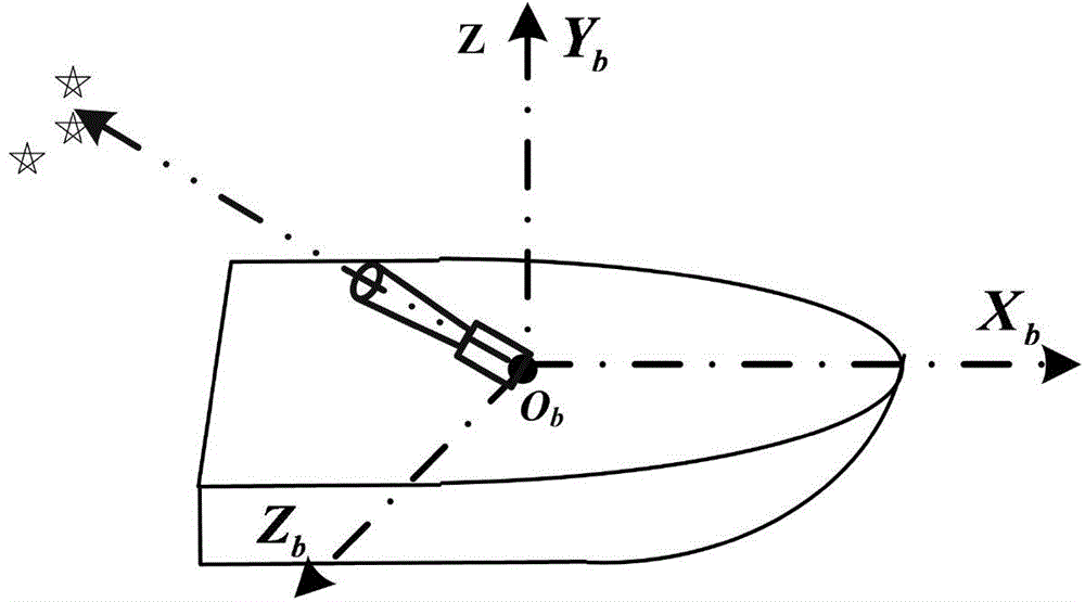
[0019] combine figure 1 and figure 2 Describe this embodiment, the method for calibrating the installation angle of a ship-borne large-field-of-view high-precision star sensor, the method is realized by the following steps: the coordinate system involved in this embodiment has CIS-earth-centered inertial coordinate system (J2000.0 coordinate system ), MT—instantaneous flat equator Earth-centered system, CT—instantaneous true equatorial Earth-centered system, ET—quasi-Earth-fixed coordinate system, CTS—Earth-fixed coordinate system, DP—inertial navigation horizon system, b—deck coordinate system, s— Star sensor coordinate system. figure 1 is the deck coordinate O b -X b Y b Z b Schematic diagram of the installation of the star sensor. o b x b Axis in deck plane, O b Y b In the vertical deck plane, O b Z b Determined by the right-hand rule. figure 2 It is a schematic diagram of transformation from the earth-centered inertial coordinate system of the star sensor to...


PUM


Abstract

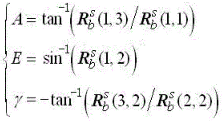
The invention provides a mounting angle calibration method for an onboard large-view-field high-precision star sensor and relates to the field of attitude control ground application of spacecrafts. The invention provides the mounting angle calibration method for the onboard large-view-field high-precision star sensor to solve the problems. The method provided by the invention comprises the following steps: 1, calibrating a null position difference and a collimation difference by a calibration theodolite under a ship docking condition; calibrating parameters including a main point, a focal distance, optical distortion and the like by the star sensor; 2, resolving a ship body attitude matrix by the calibration theodolite; 3, measuring by the star sensor to obtain an attitude matrix under a J2000.0 coordinate system and carrying out precession, nutation, rotation, polar motion and ship position correction to obtain the attitude matrix of the star sensor under an inertial navigation horizon system; 4, resolving an attitude angle of the star sensor under the inertial navigation horizon system and selecting an astronomical refraction model to carry out elevation correction; reconstructing the attitude matrix; 5, calculating the mounting matrix of the star sensor and resolving a mounting angle.

Description

technical field [0001] The invention relates to the ground application field of spacecraft attitude control, in particular to a method for calibrating the mounting angle of a star sensor. According to the principle of the star sensor attitude determination algorithm, the installation angle of the ship-borne large-field-of-view high-precision star sensor is accurately calibrated. Background technique [0002] The star sensor is a high-precision attitude sensor that uses stars as a reference. It can be settled by detecting stars in different positions on the celestial sphere. It has the ability of autonomous navigation and plays an important role in the control system and attitude measurement process of various aircraft. effect. The star sensor has the characteristics of good concealment, wide application range, high reliability, high precision, and can work independently around the clock. [0003] my country's aerospace survey ship adopts a single-station positioning system...

Claims


Application Information

Patent Timeline
IPC IPC(8): G01C25/00
CPCG01C25/00
Inventor 郭敬明何昕魏仲慧何家维张磊张同双
Owner CHANGCHUN INST OF OPTICS FINE MECHANICS & PHYSICS CHINESE ACAD OF SCI
Learn More