An off-axis unobstructed extreme ultraviolet projection lithography objective

An unobstructed, extreme ultraviolet technology, applied in optics, optical components, instruments, etc., can solve problems such as inability to meet extreme ultraviolet high-resolution imaging requirements, unfavorable processing and manufacturing, and failure to achieve imaging accuracy.

Active Publication Date: 2016-01-13
BEIJING INSTITUTE OF TECHNOLOGYGY
View PDF5 Cites 0 Cited by
  • Summary
  • Abstract
  • Description
  • Claims
  • Application Information

AI Technical Summary

Problems solved by technology

However, the imaging distortion of this system reaches 12nm, and the imaging accuracy cannot be achieved.
[0007] The existing off-axis unobstructed 6-mirror design is the third structure in US2012 / 0069314A1. This structure has very good imaging performance, but the total length of the system reaches 1849mm, which is not conducive to processing and manufacturing, and the numerical aperture is 0.38. Improving the resolution of the lithography system is not effective
[0008] The existing unobstructed 6 mirrors design the structure in Chinese patent CN102608737. This structure has better imaging performance, but the numerical aperture is only 0.25, which cannot meet the extreme ultraviolet high resolution imaging requirements.

Method used


Image

  • An off-axis unobstructed extreme ultraviolet projection lithography objective
  • An off-axis unobstructed extreme ultraviolet projection lithography objective
  • An off-axis unobstructed extreme ultraviolet projection lithography objective

Examples


Embodiment Construction

[0044] The present invention will be described in detail below with reference to the accompanying drawings and examples.

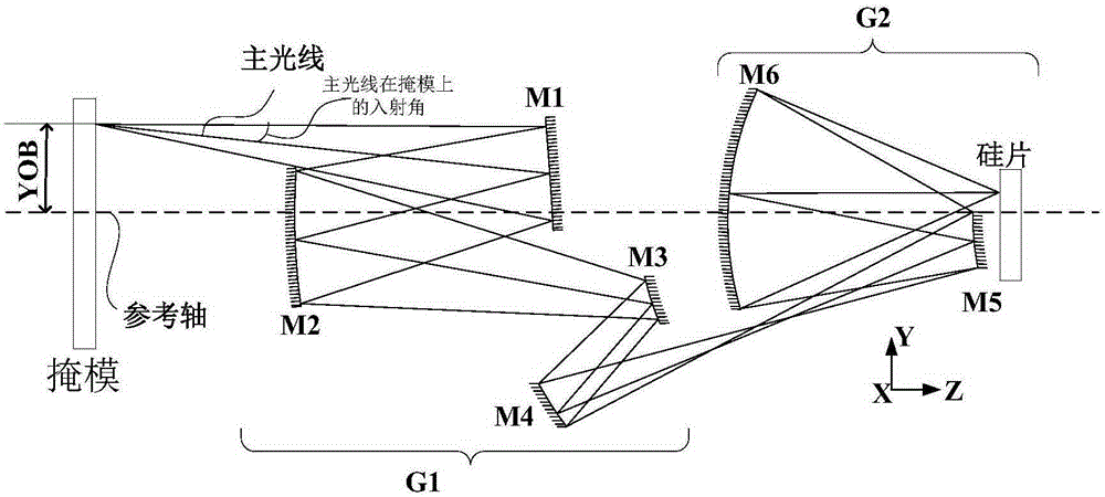
[0045] Such as figure 1 As shown, the extreme ultraviolet projection lithography objective lens of the present invention is an off-axis optical system, and has no rotational symmetry axis, its object plane is the plane where the mask is located, and the image plane is the plane where the silicon wafer is located; the objective lens includes a first lens group And the second mirror group, wherein the first mirror group includes four mirrors: the first mirror M1, the second mirror M2, the third mirror M3 and the fourth mirror M4; the second mirror group includes two mirrors , are the fifth mirror M5 and the sixth mirror M6; the positional relationship along the optical path direction is: the first mirror M1, the second mirror M2, the third mirror M3, the fourth mirror M4, and the fifth mirror M5 and the sixth mirror M6.

[0046] The working process of the ...


PUM


Abstract

The invention discloses an off-axis unblocked extreme ultraviolet lithography objective lens. A fifth reflector and a sixth reflector are rotated and slanted, a middle image can be imaged on an image face of the extreme ultraviolet lithography objective lens through the fifth reflector and sixth reflector in an unblocked mode, and the problem of edge view field optical MFA and resolving power reduction caused by light path blocking exists between the upper edge of the fifth reflector and the lower edge of the sixth reflector after the system NA is increased can be solved. Design parameters of six lenses are improved, the image space NA of the extreme ultraviolet lithography objective lens achieves 0.4, and the lithography resolving power is accordingly improved. The width of the image space scanning direction view field achieves 1.5 mm, and the productivity of silicon wafers is guaranteed. Parameters of non-rotational symmetry free hook faces on the six lenses are improved, the obtained projective lithography objective lens has the excellent imaging quality, all values of view field wave aberration RMSs are smaller than 0.0442 lambda, and the full view field change distortion is smaller than 1.85 nm.

Description

technical field [0001] The invention relates to an off-axis unobstructed extreme ultraviolet projection lithography objective lens, which can be used in a scanning-step extreme ultraviolet lithography system and belongs to the technical field of optical design. Background technique [0002] As the most promising next-generation lithography technology, extreme ultraviolet lithography can meet the industrialization requirements of semiconductor manufacturing at 16nm and higher technology nodes. Extreme ultraviolet lithography uses a light source with a wavelength of 11-15nm for illumination. Since almost all optical materials have strong absorption in this wavelength band, the extreme ultraviolet lithography system uses reflective optical components coated with reflective films. As the core component of the extreme ultraviolet lithography system, the extreme ultraviolet projection lithography objective lens has the design requirements of high resolution, high image quality and...

Claims


Application Information

Patent Timeline
Patent Type & Authority Patents(China)
IPC IPC(8): G02B17/06G02B13/14
Inventor 李艳秋刘岩刘菲曹振
Owner BEIJING INSTITUTE OF TECHNOLOGYGY
Why Eureka
Try Eureka