Stepped steel ball lock hydraulic cylinder

A steel ball lock and hydraulic cylinder technology, which is applied in the field of locking hydraulic cylinders, can solve the problems of high oil source and oil circuit requirements, low yield and high processing difficulty, avoiding the problem of unreliable locking, small occupied space, compact effect

Active Publication Date: 2015-11-25
CHANGZHI QINGHUA MACHINERY FACTORY +1
View PDF6 Cites 0 Cited by
  • Summary
  • Abstract
  • Description
  • Claims
  • Application Information

AI Technical Summary

Problems solved by technology

[0004] Screw screw piston rod locking is automatic operation, but each hydraulic cylinder requires a dedicated power mechanism and power source, the additional system is complicated and the mechanism is huge, which does not meet the requirements of simple and fast equipment hardcover
[0005] The conical surface friction compression locking mechanism is simple, but the reverse thrust of the conical surface compression is limited, which does not meet the needs of large-tonnage equipment
[0006] The interference locking of the mating surface has very strict requirements on the amount of interference. If the amount of interference is large, the unlocking pressure is high, and the requirements for oil source and oil circuit are high; the amount of interference is small, the locking force is small, and the locking is unreliable. At the same time, the requirements for product raw materials, machining processes, and heat treatment are correspondingly increased, resulting in difficult processing and low yield, which is not suitable for high-efficiency development and energy consumption reduction requirements.

Method used


Image

  • Stepped steel ball lock hydraulic cylinder
  • Stepped steel ball lock hydraulic cylinder
  • Stepped steel ball lock hydraulic cylinder

Examples


Embodiment 1

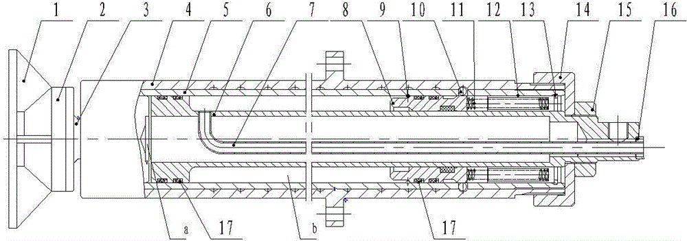
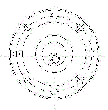
[0027] Such as Figure 1-Figure 3 As shown, there is a graded steel ball locking hydraulic cylinder, including an outer cylinder 4, an inner cylinder 5, a piston rod 6, an oil pipe 7, a locking piston 8, a steel ball 10, a spring 11, a spring seat 12 and a cylinder cover 14. The outer cylinder 4 is threadedly connected with the cylinder head 14, and the inner wall of the outer cylinder 4 is provided with multiple radial grooves. , the outer wall of the inner cylinder 5 is provided with a circle of radial circumferential holes that can place steel balls 10, the piston rod 6 and the locking piston 8 are all arranged in the inner chamber of the inner cylinder 5, and one end of the piston rod 6 is connected 5. The inner wall is clearance fit, and the other end passes through the cylinder head 14 and is fixed by the lock nut 15. The inner wall of the locking piston 8 is in clearance fit with the piston rod 6 and the inner wall can be connected with the inner cavity of the piston ro...

Embodiment 2

[0038] Such as Figure 1-Figure 3 As shown, there is a graded steel ball locking hydraulic cylinder, including an outer cylinder 4, an inner cylinder 5, a piston rod 6, an oil pipe 7, a locking piston 8, a steel ball 10, a spring 11, a spring seat 12 and a cylinder cover 14. The outer cylinder 4 is threadedly connected with the cylinder head 14, and the inner wall of the outer cylinder 4 is provided with multiple radial grooves. , the outer wall of the inner cylinder 5 is provided with a circle of radial circumferential holes that can place steel balls 10, the piston rod 6 and the locking piston 8 are all arranged in the inner chamber of the inner cylinder 5, and one end of the piston rod 6 is connected 5. The inner wall is clearance fit, and the other end passes through the cylinder head 14 and is fixed by the lock nut 15. The inner wall of the locking piston 8 is in clearance fit with the piston rod 6 and the inner wall can be connected with the inner cavity of the piston ro...


PUM


Abstract

The invention discloses a step ball lock-up hydraulic cylinder and belongs to the technical field of lock-up hydraulic cylinders, aiming to provide a step closed type lock-up hydraulic cylinder with the feature that any optional stroke thereof can be subjected to mechanical locking automatically. The technical scheme includes that an outer barrel is in threaded connection with a cylinder head, and multiple radial grooves are formed on the inner wall of the outer barrel; an inner barrel is disposed in an inner cavity of the outer barrel and in clearance fit with the inner wall of the outer barrel; a piston rod and a lock piston are arranged in an inner cavity of the inner barrel; one end of the piston rod is in clearance fit with the inner wall of the inner barrel, the other end of the piston rod runs through the cylinder head to be fixed by a nut, the inner wall of the lock piston is in clearance fit with the piston rod, an groove and a boss are arranged on the outer wall of the lock piston, and the boss is in clearance fit with the inner wall of the inner barrel; a steel-wire retainer ring is arranged at the end, away from the cylinder head, of the lock piston, the other end of lock piston is elastically connected with one end of a spring, and the other end of the spring is disposed in an inner cavity of a spring holder; one end of an oil tube penetrates an inner cavity of the piston rod to be communicated with the inner cavity of the inner barrel, and the other end of the oil tube extends out of the inner cavity of the piston rod.

Description

technical field [0001] The utility model relates to a locking hydraulic cylinder with graded steel balls, which belongs to the technical field of locking hydraulic cylinders. Background technique [0002] With the improvement of mechanization in all walks of life in the world, the application of mechanical locking hydraulic cylinders is becoming more and more extensive. The existing locking hydraulic cylinders are divided into two types: locking at both ends of the stroke and locking at the required stroke section according to the locking position. The steel ball lock is the lock at both ends of the stroke, and the lock of the stroke section needs to be in the form of interference of the mating surface, external pin balls, external compression sleeves, screw screw piston rods, and conical surface friction compression. [0003] The locking of the external pin bead and the external compression sleeve is manual locking, which is not suitable for modern operation. [0004] Scre...

Claims


Application Information

Patent Timeline
Patent Type & Authority Patents(China)
IPC IPC(8): F15B15/14F15B15/26
Inventor 武丽明杨护红韩晓胡秀全孙涛郭金龙张艳云景小海王浩
Owner CHANGZHI QINGHUA MACHINERY FACTORY
Why Eureka
Try Eureka