
Test tube clamp

A technology of test tube clamps and test tubes, which is applied in the field of experimental equipment, can solve the problems of increased test tube wear, danger to experimenters, wrong gripping and pinching of upper clamps, etc., and achieves the effects of simple structure, convenient use, and avoidance of falling

Inactive Publication Date: 2014-07-02
QINGDAO UNITED INNOVATION TECHN SERVICES PLATFORM
View PDF0 Cites 6 Cited by
  • Summary
  • Abstract
  • Description
  • Claims
  • Application Information

AI Technical Summary

Problems solved by technology

Conventional test tube clamps are only connected by metal wires with springs to connect the upper and lower clamping blocks. Due to the poor clamping function of the spring, it is easy to cause loose clamping and cause the test tube to fall; on the other hand, since the upper clamping block can move, During the experiment, it is easy to misoperate and pinch the upper clamp, causing the test tube to fall
This not only increases the wear and tear of the test tube, but also causes the experiment to be terminated and re-tested, which not only wastes time, manpower, material and financial resources, but more importantly, if the test tube contains toxic reagents, it will cause danger and injury to the experimenters.

Method used


Image

  • Test tube clamp
  • Test tube clamp
  • Test tube clamp

Examples


Embodiment 1

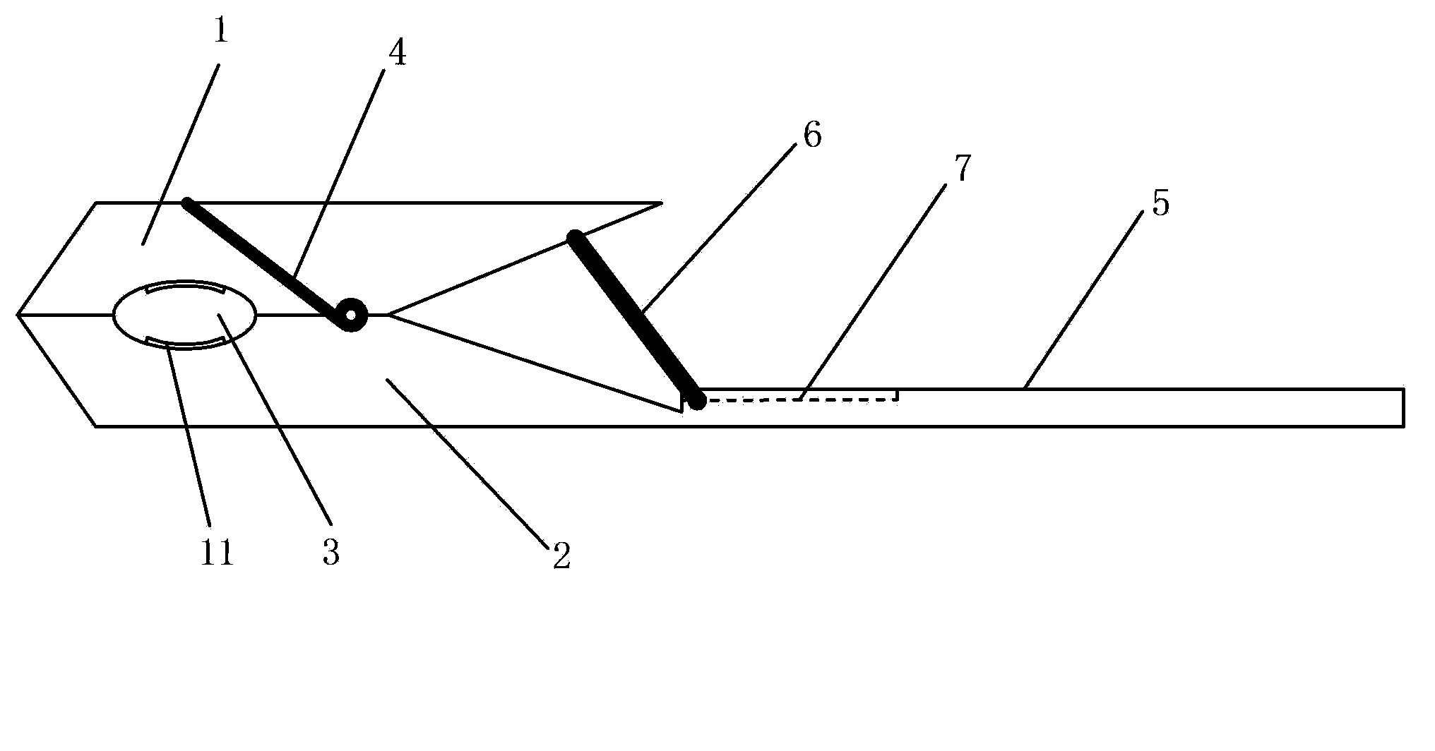
[0017] Depend on figure 1 , 2 As can be seen from the test tube clamp shown in 3, it includes a concave upper clamp block and a lower clamp block, a hand-held part connected with the lower clamp block, the upper and lower clamp blocks are connected by a metal wire with a spring, and the upper and lower clamp blocks The recessed part forms a space for clamping the test tube, and a supporting rod capable of supporting the upper clamping block is provided at the connection position between the handle part and the lower clamping block, and the supporting rod is provided with a fixing device. Wherein, the fixing device is a bolt that runs through the handle part and one end of the support rod, and nuts are arranged at both ends of the bolt. The handle is provided with a slot for storing the support rod. The concave parts of the upper clamping block and the lower clamping block are provided with anti-skid gaskets, which can better prevent the test tube from slipping.

[0018] Whe...

Embodiment 2

[0020] Depend on figure 1 , 2 As can be seen from the test tube clamp shown in 4, it includes a concave upper clamp block and a lower clamp block, a hand-held part connected with the lower clamp block, the upper and lower clamp blocks are connected by a metal wire with a spring, and the upper and lower clamp blocks The recessed part forms a space for clamping the test tube, and a supporting rod capable of supporting the upper clamping block is provided at the connection position between the handle part and the lower clamping block, and the supporting rod is provided with a fixing device. Wherein, the fixing device is a screw that runs through the handle part and one end of the support rod, and the screw is provided with a nut. The handle is provided with a slot for storing the support rod. The concave parts of the upper clamping block and the lower clamping block are provided with anti-skid gaskets, which can better prevent the test tube from slipping.

[0021] When in use,...


PUM


Abstract

The invention relates to a test tube clamp. The test tube clamp comprises an upper clamping block and a lower clamping block with recesses, and a handheld part connected with the lower clamping block, wherein the upper clamping block and the lower clamping block are connected through a metal wire with a spring; a space for clamping test tubes is formed between the recesses of the upper and lower clamping blocks; a supporting rod which can support the upper clamping block is arranged at the joint of the handheld part and the lower clamping block. The test tube clamp has the beneficial effects that the supporting rod which can support the upper clamping block is arranged at the joint of the handheld part and the lower clamping block, and the supporting rod is provided with a fixing device for fixing the upper and lower clamping blocks, so that the test tubes are prevented from dropping, the experimental process is safe and reliable, and the test tube clamp is simple in structure and convenient to use.

Description

technical field [0001] The invention relates to the field of experimental instruments, in particular to a test tube clamp. Background technique [0002] During the experiment, it is often necessary to use the test tube clamp to hold the test tube, such as heating the liquid in the test tube. Conventional test tube clamps are only connected by metal wires with springs to connect the upper and lower clamping blocks. Due to the poor clamping function of the spring, it is easy to cause loose clamping and cause the test tube to fall; on the other hand, since the upper clamping block can move, During the experiment, it is easy to mishandle and pinch the upper clamp, causing the test tube to fall. This not only increases the wear and tear of the test tube, but also causes the experiment to be terminated and re-tested, which not only wastes time, manpower, material and financial resources, but more importantly, if the test tube contains toxic reagents, it will cause danger and inju...

Claims


Application Information

Patent Timeline
Patent Type & Authority Applications(China)
IPC IPC(8): B01L9/06
Inventor 胡云雪田书显
Owner QINGDAO UNITED INNOVATION TECHN SERVICES PLATFORM
Learn More