
Catalyst regenerating device

A regeneration device and catalyst technology, applied in the direction of catalyst regeneration/reactivation, physical/chemical process catalysts, chemical instruments and methods, etc., can solve the problems of complex structure, increased tar amount, high energy consumption, etc., and achieve sufficient and uniform heating , Improve catalytic efficiency, work stably and reliably

Active Publication Date: 2014-07-02
张家港市天源机械制造有限公司
View PDF6 Cites 2 Cited by
  • Summary
  • Abstract
  • Description
  • Claims
  • Application Information

AI Technical Summary

Problems solved by technology

The structure of the catalyst regeneration device with the above-mentioned structure is relatively complicated, and the energy consumption is also relatively large. Moreover, when the catalyst is heated, due to the limitation of the heating method, the catalyst located in the combustion furnace is heated unevenly, which will directly affect the catalytic efficiency of the catalyst. , so that the biomass raw material cannot be fully gasified, which will inevitably increase the amount of tar produced after the gasification of the biomass raw material, and greatly reduce the gas calorific value of the combustible gas

Method used


Image

  • Catalyst regenerating device
  • Catalyst regenerating device
  • Catalyst regenerating device

Examples


Embodiment Construction

[0013] The technical solutions of the present invention will be further described in detail below in conjunction with the accompanying drawings and preferred embodiments.

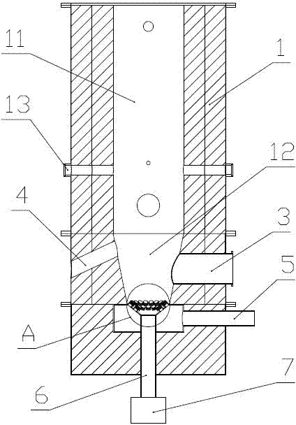
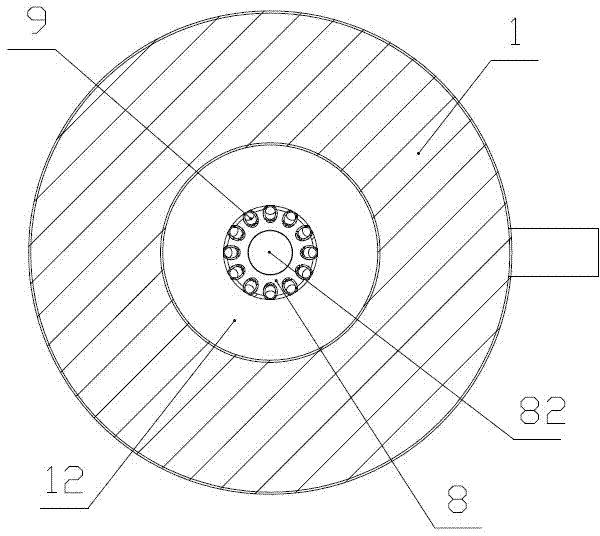
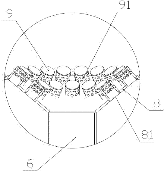
[0014] Such as figure 1 , figure 2 , image 3 As shown, the catalyst regeneration device of the present invention includes: a combustion furnace 1, an inlet 3 and an outlet 4 communicating with the inner chamber of the combustion furnace are respectively arranged on the side wall of the lower half of the combustion furnace 1. The bottom of the inner cavity of the combustion furnace is provided with an injection device that can quickly heat the catalyst to the required temperature and then output it from the outlet. The injection device is located below the inlet 3 and the outlet 4. The structure of the injection device is: The bottom is provided with a downwardly recessed concave baffle 8, and on the concave surface of the concave baffle 8, some injection pipes 9 are arranged, and on the side wall of the...


PUM


Abstract

The invention discloses a catalyst regenerating device. The catalyst regenerating device comprises a combustion furnace, wherein the side wall of the combustion furnace is respectively provided with an inlet and an exhaust outlet which are respectively communicated with an inner cavity of the combustion furnace; the bottom of the inner cavity of the combustion furnace is provided with an ejecting device which enables a catalyst to be rapidly heated to the required temperature and then to be output from the exhaust outlet; the ejecting device is positioned below the inlet. The ejecting device is structurally characterized in that the bottom of the inner cavity of the combustion furnace is provided with concave baffles sinking downward; the concave surfaces of the concave baffles are provided with a plurality of ejecting pipes; a plurality of ejecting holes are formed in the side walls of the ejecting pipes; the top parts of the ejecting pipes are sealed, and the concave baffles corresponding to the bottom of each ejecting pipe are respectively provided with through holes communicated with each ejecting pipe; the side wall of the combustion furnace is provided with an air inlet communicated with each through hole; the air inlet is communicated with each ejecting pipe by each through hole. The catalyst regenerating device provided by the invention is simple in structure, is low in energy consumption, and greatly improves the catalytic efficiency of the catalyst.

Description

technical field [0001] The invention relates to the field of biomass energy equipment, in particular to a catalyst regeneration device. Background technique [0002] In the context of the gradual depletion of fossil energy, biomass energy has become the most ideal alternative energy due to its renewability, low pollution and wide distribution. mainly waste and wood waste. Biomass raw materials can generate H 2 , CO and CH 4 In order to promote the gasification of biomass raw materials, it is generally necessary to use catalysts in combination to mix the biomass raw materials and high-temperature catalysts evenly and exchange heat sufficiently before transporting the biomass raw materials and catalysts to the gasifier for gasification reaction. After the catalyst is used, it needs to be heated and regenerated at high temperature before it can continue to be used. At present, the catalyst regeneration device used to heat the catalyst to reactivate and regenerate it include...

Claims


Application Information

Patent Timeline
Patent Type & Authority Applications(China)
IPC IPC(8): B01J38/38
Inventor 赵达斌
Owner 张家港市天源机械制造有限公司
Learn More