Magnetic field data modem

A modem and data modulation technology, applied in the field of data communication, to achieve the effect of easy relocation, easy positioning and small assembly

Inactive Publication Date: 2014-06-25
KONINKLJIJKE PHILIPS NV
View PDF5 Cites 1 Cited by
  • Summary
  • Abstract
  • Description
  • Claims
  • Application Information

AI Technical Summary

Problems solved by technology

Light and infrared communications can pass through such windows, but require window space and location-specific equipment

Method used


Image

  • Magnetic field data modem
  • Magnetic field data modem
  • Magnetic field data modem

Examples


Embodiment Construction

[0022] refer to figure 1 , the MR room 10 houses the MR scanner 12 and its associated patient bed or support 14 . The walls 16 as well as the floor 18 and ceiling (not shown) are covered by a grounded conductive surface (eg, copper sheet) 20 to form a Faraday shield. The door 22 is large enough to pass a patient gurney and is also shielded. A door lock (not shown) cams the door tightly closed to ensure contact between the door and the wall shield without any gaps.

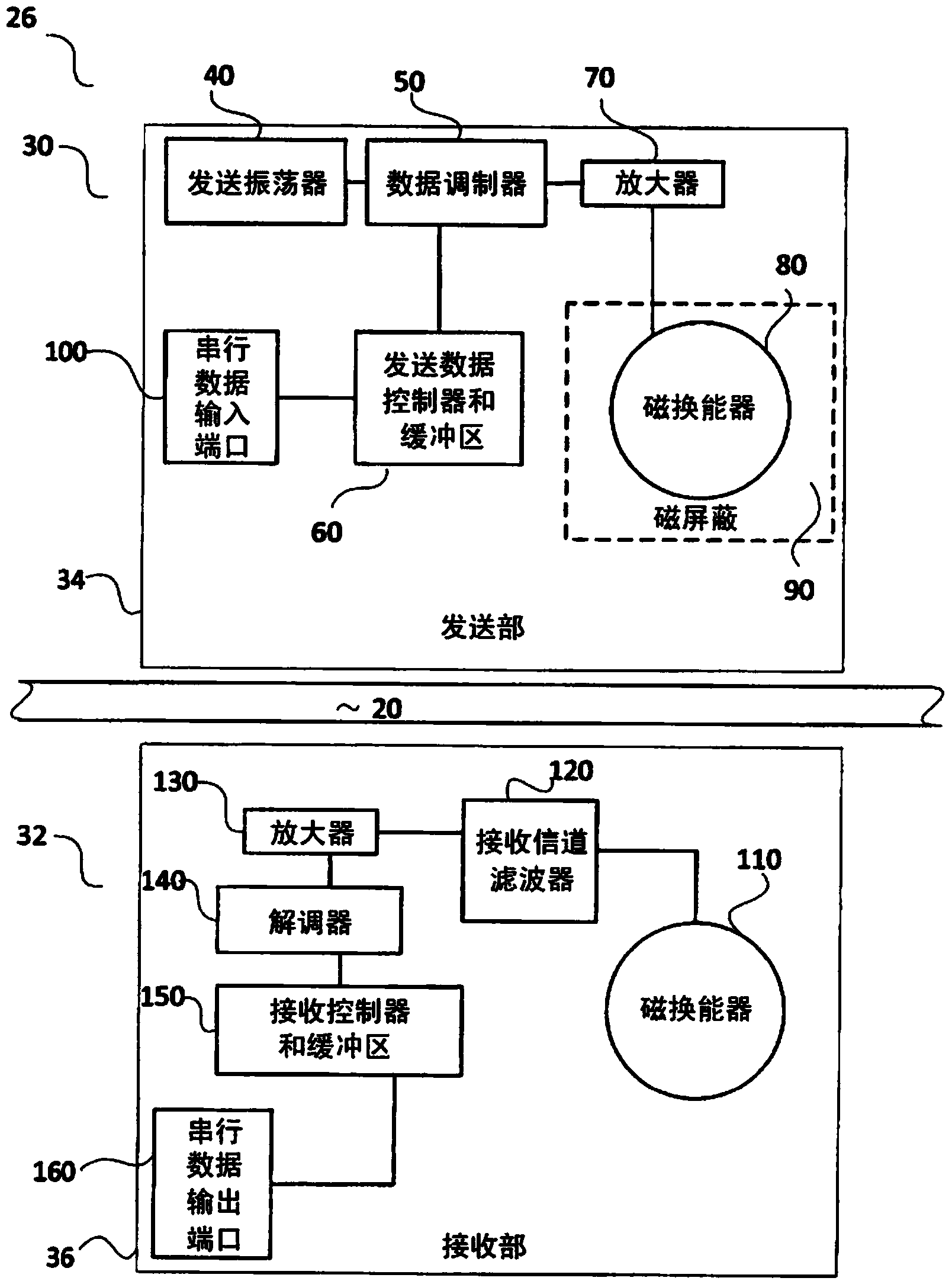
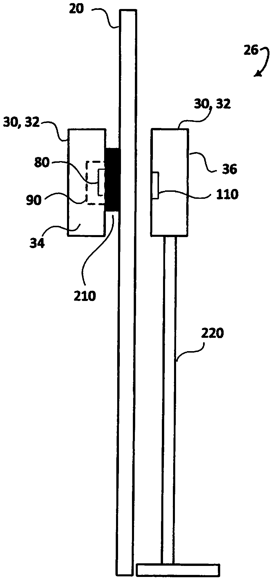
[0023] Indoor equipment 24 (such as patient monitoring equipment, MR control unit, MR signal output unit, etc.) is connected to a magnetic data modem 26 . The modem is connected to an operator console 28 which processes data received from the modem to generate displays, store records, etc., and / or send signals via the modem to the MR room. Magnetic data modem 26 includes similar indoor and outdoor modem units 30 and 32, respectively.

[0024] refer to figure 2 , shows the components of one embodiment of the m...


PUM


Abstract

A magnetic field modem (26) includes an electro-magnetic radiation shielded (90) transmitter section (34) and a receiver section (36). The electro-magnetic radiation shielded (90) transmitter section (34) modulates data and transmits the data via a magnetic field through a radio frequency shield (20). The receiver section (34) receives the magnetic field through the radio frequency shield (20) and demodulates the data. The transmitter section includes an oscillator (40), a modulator (50), an amplifier (70), a magnetic transducer (80), and a non-ferrous magnetic shield (90). The oscillator (40) generates a carrier signal. The modulator (50) connects to the oscillator (40) and modulates the carrier signal with the data. The amplifier (70) connects to the modulator (50) and amplifies the modulated carrier signal. The magnetic transducer (80) connects to the amplifier (70) and converts the modulated carrier signal into a modulated magnetic signal. The non-ferrous magnetic shield (90) shields the magnetic transducer (80) and blocks emitted electro-magnetic radiation.

Description

technical field [0001] This application relates to data communications, modems, and magnetic fields, and more particularly to data communications in a magnetic resonance imaging environment. Background technique [0002] MRIs are done in a room that is shielded from radio frequency waves. Radio frequency (RF) coils are used to excite magnetic resonance in the subject and to receive weak radio frequency magnetic resonance signals. External radio frequency waves can negatively affect imaging. MRI scanners are usually installed in rooms that are shielded from external radiation from radio frequency. Commonly used shields are non-ferrous shields (such as copper or aluminum), which cover the walls, ceiling and floor surfaces of the MR room. The shielding of the room is sometimes called a Faraday cage. [0003] Communications to or from the scanner, subject, or device associated with an external source pass through the shield. Data communication between the control room and t...

Claims


Application Information

Patent Timeline
Patent Type & Authority Applications(China)
IPC IPC(8): H04B5/00
CPCH04L27/38H04B5/0031H04L27/36H04B5/0087
Inventor R·哈韦尔O·R·哈里斯
Owner KONINKLJIJKE PHILIPS NV
Why Eureka
Try Eureka