
Heating machine structure capable of improving sealing stability

A heater and stability technology, applied in the mechanical field, can solve problems such as seal failure, heater change, air pressure change, etc., to achieve the effect of improving sealing and solving seal failure

Inactive Publication Date: 2014-06-25
CHENGDU QIAOFENG TECH DEV
View PDF4 Cites 1 Cited by
  • Summary
  • Abstract
  • Description
  • Claims
  • Application Information

AI Technical Summary

Problems solved by technology

[0004] The purpose of the present invention is to overcome the problem of seal failure due to changes in the air pressure of the existing heater after heating, and to design a heater structure that can increase the stability of the seal. The heater structure utilizes a mechanically locked structure. It can keep the seal fixed under changing conditions, improve the sealing performance, and solve the problem that the air pressure of the existing heating machine changes after heating and the seal fails.

Method used


Image

  • Heating machine structure capable of improving sealing stability

Examples


Embodiment 1

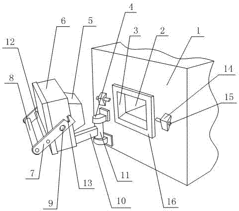
[0015] Such as figure 1 As shown, the heater structure capable of increasing the sealing stability includes a sealed casing 1, the side wall of the casing 1 is provided with a feed port 2 communicating with the inside of the casing 1, and a heat preservation device is sleeved in the feed port 2. Cover 16, heat preservation cover 16 is provided with through hole 3, and the side wall that is provided with feed port 2 on described housing 1 is provided with sealing block 5, and sealing block 5 is the trapezoidal body structure that fits with through hole 3, and sealing block 5 The side wall of the housing 1 is in seamless contact with the side wall of the through hole 3; the housing 1 is provided with two locking mechanisms on the side wall of the material opening 2, and the locking mechanisms are symmetrically arranged on both sides of the insulation cover 16. The tightening mechanism comprises a fixed block 14 and a locking pin 15, and the locking pin 15 passes through the fixi...

Embodiment 2

[0017] Such as figure 1 As shown, on the basis of Embodiment 1, two fixing buckles 4 are arranged on the side wall of the housing 1 provided with the feed port 2, the fixing buckles 4 are arranged on the same vertical line, and the fixing buckles 4 are arranged between There is a rotating shaft 11, the two ends of the rotating shaft 11 pass through one of the fixing buckles 4 respectively, and the rotating shaft 11 can rotate in the fixing buckle 4 around its axis, the outer wall of the rotating shaft 11 is fixed with a rotating handle 10, and the rotating handle 10 Arranged between the two fixing buckles 4 , the end of the rotating handle 10 away from the rotating handle 10 is fixed to the side wall of the spacer block 6 , and the fixing buckle 4 is arranged below the fixing block 14 . In order to be able to realize the rotation of the rotating handle 10 to drive the isolation block 6, and to insert the sealing block 5 into the through hole 3, a rotating mechanism needs to be...


PUM


Abstract

The invention discloses a heating machine structure capable of improving the sealing stability. A material opening communicated with the inner portion of a shell is formed in the side wall of the shell. A thermal insulation sleeve is sleeved with the material opening. A through hole is formed in the thermal insulation sleeve. A sealing block is arranged on the shell and of a trapezoid body structure matched with the through hole. The side wall of the sealing block makes seamless contact with the side wall of the through hole. Locking mechanisms are arranged on the shell and symmetrically arranged on the two sides of the thermal insulation sleeve. Each locking mechanism comprises a fixed block and a locking pin, wherein the locking pin penetrates through the fixed block. An isolation block is fixed to the sealing block. Connecting plates are symmetrically arranged on the side walls of the isolation block respectively. Hinge pins are arranged on the connecting plate. One end of each hinge pin is arranged inside the isolation block after penetrating through the corresponding connecting plate. The top ends of the connecting plates cave inwards to form through grooves communicated with the symmetrical side walls of the isolation block. One end of each locking pin is arranged inside the corresponding through groove. The mechanical locking structure is adopted for the heating machine structure, and therefore fixed sealing can be kept under the condition that internal pressure changes, and sealing performance is improved.

Description

technical field [0001] The invention relates to a structure, in particular to a heating machine structure capable of increasing sealing stability, and belongs to the field of machinery. Background technique [0002] Heating is the process by which a heat source transfers thermal energy to a cooler object to make it hotter. According to the heat energy obtained, it can be divided into two types: direct and indirect. Direct heat source heating is to directly add heat energy to materials, such as flue gas heating, electric current heating and solar radiation heating. Indirect heat source heating is to add the heat energy of the above-mentioned direct heat source to an intermediate heat carrier, and then the intermediate heat carrier transfers the heat energy to the material, such as steam heating, hot water heating, mineral oil heating, etc. In the metallurgical industry, heating furnaces customarily refer to industrial furnaces that heat metals to rolling to forging temperat...

Claims


Application Information

Patent Timeline
IPC IPC(8): F27B9/36
Inventor 王勇
Owner CHENGDU QIAOFENG TECH DEV
Learn More