
Ring-beam reinforcing connection structure and ring-beam construction method

A technology for connecting structures and construction methods, which is applied in the direction of building construction and construction, and can solve problems such as low connection strength between steel pipe columns and floor concrete, difficult quality assurance, warping and deformation of ring beams, etc.

Active Publication Date: 2014-06-25
CHINA CONSTR EIGHT ENG DIV CORP LTD
View PDF5 Cites 4 Cited by
  • Summary
  • Abstract
  • Description
  • Claims
  • Application Information

AI Technical Summary

Problems solved by technology

[0004] The purpose of the present invention is to overcome the defects of the prior art, and provide a ring beam steel bar connection structure and a ring beam construction method, which can solve the problem of warping and deformation of the ring beam in the existing steel pipe column ring beam construction method, difficulty in installation, and problems between the steel pipe column and the floor concrete. Problems such as low connection strength, difficult construction of ring beam joints, and difficult quality assurance

Method used


Image

  • Ring-beam reinforcing connection structure and ring-beam construction method
  • Ring-beam reinforcing connection structure and ring-beam construction method
  • Ring-beam reinforcing connection structure and ring-beam construction method

Examples


Embodiment Construction

[0028] The present invention will be further described below with reference to the accompanying drawings and specific embodiments.

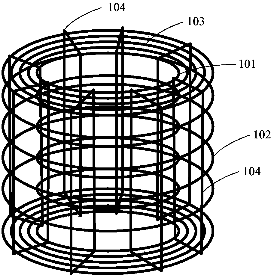
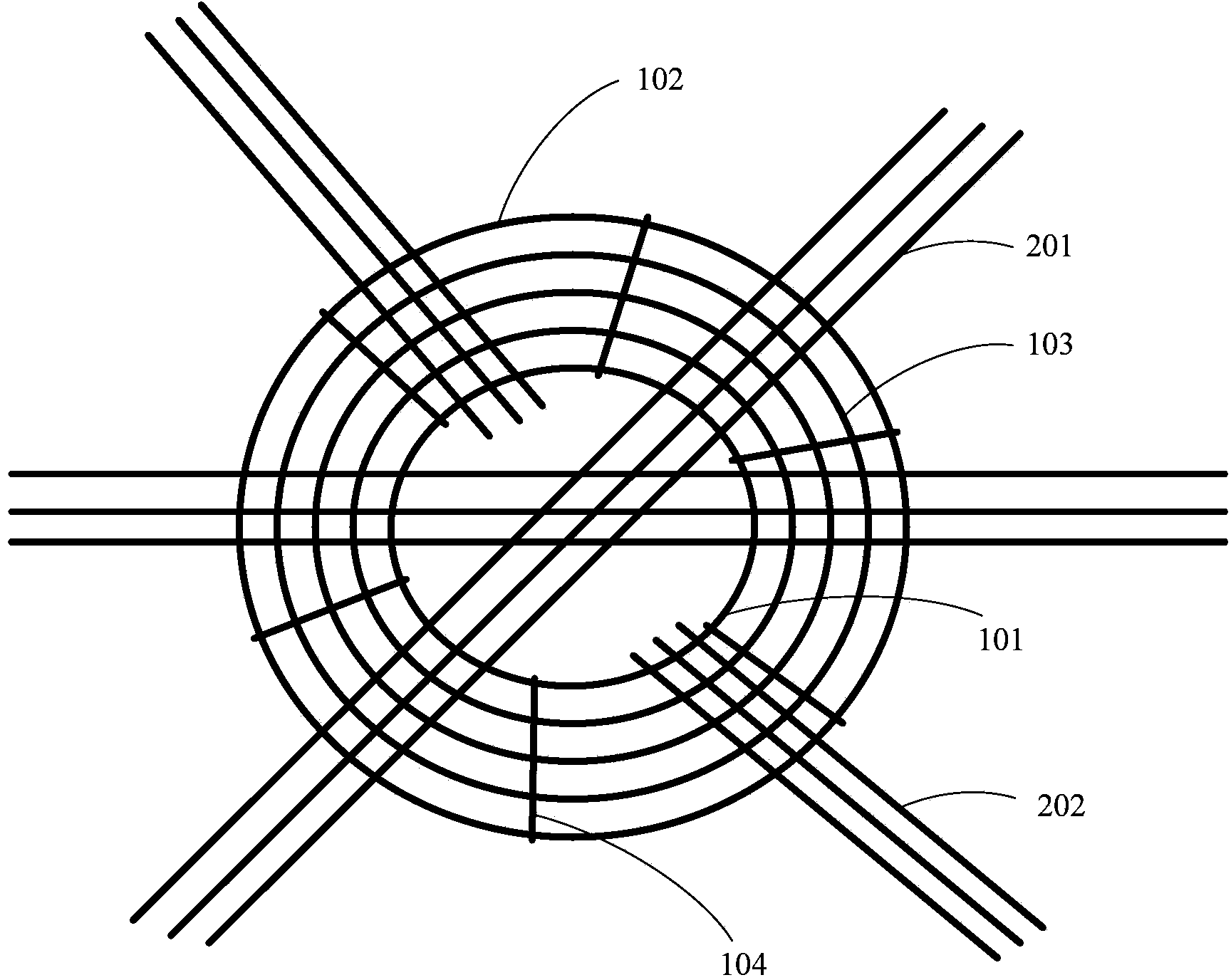
[0029] figure 1 A schematic diagram of the three-dimensional structure of the ring beam reinforcement cage in the ring beam reinforcement connection structure of the present invention is shown. figure 2 A section view showing the ring beam reinforcement cage and beam-column reinforcement connection. image 3 Top view showing ring beam reinforcement cage and floor reinforcement connections. The invention connects the floor steel bar and the beam-column steel bar through the ring beam steel bar cage, so that the floor and the beam and column can be well anchored together, forming a whole at the floor and enhancing the structural strength. The inner ring beam, the outer ring beam and the ring beam are connected by the beam longitudinal bars to form a ring beam reinforcement cage with an integrated structure, which solves the problem of warping an...


PUM


Abstract

The invention relates to a ring-beam reinforcing connection structure and a ring-beam construction method. The ring-beam reinforcing connection structure comprises a ring-beam reinforcing cage, beam column reinforcing ribs and floor reinforcing ribs. The ring-beam reinforcing cage comprises an inner ring beam, an outer ring beam, annular beams and longitudinal beam ribs, and the ring-beam beams and the longitudinal beam ribs are different in diameter and are arranged between the inner ring beam and the outer ring beam. The longitudinal beam ribs are connected with the inner ring beam, the outer ring beam and the annular beams in an enclosed manner to form an annular cylindrical structure. The beam column reinforcing ribs are penetratingly arranged in the cavity of the ring-beam reinforcing cage and connected with the same. The floor reinforcing ribs include first beam reinforcing ribs and second beam reinforcing ribs, the first reinforcing ribs penetrate the ring-beam reinforcing cage and are connected with the same, the second beam reinforcing ribs are penetratingly arranged in the ring-beam reinforcing cage, the ends of the second beam reinforcing ribs are located inside the ring-beam reinforcing cage and are connected with the same. By the adoption of the ring-beam reinforcing cage, the problem about buckling deformation produced in construction of ring beams is solved, and connection strength between beam columns and floors can be guaranteed.

Description

technical field [0001] The invention relates to the field of construction, in particular to a ring beam steel bar connection structure and a ring beam construction method. Background technique [0002] In building structural engineering, the connection between beams and columns and floors usually adopts the steel pipe column ring beam construction method, that is, ring beams are set on the steel pipe columns, joint construction is carried out according to the design shape and size, and the main bars of the surrounding beams are welded to the steel pipe. On the ring plate of the column ring beam, the ring steel bars with gradually increasing diameter are processed around the steel pipe column on the upper and lower ring plates of the steel pipe column ring beam, and the mechanical connection or welding is carried out to seal. [0003] This construction method has high requirements on the machining accuracy of the large-diameter annular steel bar surrounding the steel pipe col...

Claims


Application Information

Patent Timeline
Patent Type & Authority Applications(China)
IPC IPC(8): E04B1/58
Inventor 赵雪燕陆仕颖程海林龚煌森陈法兵
Owner CHINA CONSTR EIGHT ENG DIV CORP LTD
Learn More