
Dynamic membrane forming control method applicable to anaerobic digestion of excess sludge

A technology of excess sludge and anaerobic digestion, applied in sludge treatment, biological sludge treatment, waste fuel, etc., can solve problems such as poor solid-liquid separation, high replacement cost, and damage to dynamic membranes, and achieve gas saving Circular energy consumption, convenient upgrading and transformation, and the effect of reducing damage

Active Publication Date: 2014-06-25
TONGJI UNIV
View PDF7 Cites 11 Cited by
  • Summary
  • Abstract
  • Description
  • Claims
  • Application Information

AI Technical Summary

Problems solved by technology

However, the use of microfiltration / ultrafiltration membrane modules has the following disadvantages: the cost of membrane modules is high, and the cost of replacement is high; the instantaneous flux of membrane modules in constant flow operation mode can only be maintained at 10 L / (m 2 h) or less, and the outlet pump is usually in the intermittent suction mode, so the average flux is lower; the membrane surface needs continuous aeration to slow down the membrane fouling, and the energy consumption is high
Using biogas generated from sludge digestion to scour the surface of the membrane can effectively control membrane fouling, but at the same time it will also destroy the formation of dynamic membranes, making it in the first stage of dynamic membrane formation, during which a large number of solid particles pass through large pores. Substrate, resulting in deterioration of effluent water quality
Especially under anaerobic conditions, the particle size of sludge is usually lower than that of aerobic conditions. Compared with aerobic conditions, the destruction of dynamic membranes is more likely to lead to poor solid-liquid separation

Method used


Image

  • Dynamic membrane forming control method applicable to anaerobic digestion of excess sludge

Examples


Embodiment 1

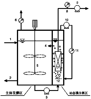
[0024] use figure 1 The process shown treats residual sludge from municipal sewage treatment plants. It is composed of the main fermentation area and the dynamic membrane separation area, of which the effective volume of the latter is only 3% of the former. The main fermentation area is equipped with mud inlet pipe 1, mud discharge pipe 2, stirring device 5 and gas metering device 6; the dynamic membrane separation area is equipped with dynamic membrane module 7, pressure gauge 8, water outlet pump 9 and biogas circulation system, the biogas The circulation system is composed of a diaphragm vacuum pump 10, a gas flow meter 11 and a biogas diffusion pipe 12; the two areas are connected by a sludge return pump 3 and a sludge return pipe 4. The remaining sludge enters the reactor system from the sludge inlet pipe 1, and is stirred and mixed by the stirring device 5 in the main fermentation area; the sludge in the main fermentation area enters the dynamic membrane separation area...

Embodiment 2

[0027] use figure 1 The process shown treats residual sludge from municipal sewage treatment plants. The sludge concentration (SS) of the sludge inlet is 5-8 g / L, and the sludge concentration (SS) of the dynamic membrane separation zone is 18-22 g / L. The dynamic membrane module 7 adopts a polyester mesh module with a pore size of 39 μm and a membrane area of ​​0.038 m 2 , the membrane flux is 15 L / (m 2 · h), using continuous membrane filtration to operate. Using the invented method to operate, in a biogas cycle cycle, the closing time of the biogas circulation is 20 minutes, the opening time is 3 minutes, and the biogas circulation intensity is 25 m 3 / (m 2 h). The turbidity of the effluent is less than 150 NTU, the SS of the effluent is less than 120 mg / L, and the physical cleaning cycle of the dynamic membrane module is 5-10 days.

Embodiment 3

[0029] use figure 1 The process shown treats residual sludge from municipal sewage treatment plants. The sludge concentration (SS) of the sludge inlet is 5-8 g / L, and the sludge concentration (SS) of the dynamic membrane separation zone is 18-22 g / L. The dynamic membrane module 7 adopts a polyester mesh module with a pore size of 39 μm and a membrane area of ​​0.038 m 2 , the membrane flux is 15 L / (m 2 · h), using continuous membrane filtration to operate. Using the invented method to operate, in a biogas cycle cycle, the closing time of the biogas circulation is 20 minutes, the opening time is 1 minute, and the biogas circulation intensity is 50 m 3 / (m 2 h). The turbidity of the effluent is less than 160 NTU, the SS of the effluent is less than 140 mg / L, and the physical cleaning cycle of the dynamic membrane module is 7-20 days.


PUM

PropertyMeasurementUnit
Apertureaaaaaaaaaa
Membrane areaaaaaaaaaaa

Abstract

The invention provides a dynamic membrane forming control method applicable to anaerobic digestion of excess sludge, and relates to a continuous dynamic membrane filtering mode of a split immersion type anaerobic dynamic membrane-biological reactor for treating excess sludge. According to the dynamic membrane control method disclosed by the invention, an intermittent operation mode of biogas circulation is set and a purpose of controlling the growth and decay rate of the dynamic membrane by setting the closing and opening time of the biogas circulation and biogas circulation strength is achieved. The dynamic membrane forming control method disclosed by the invention is coupled with conventional anaerobic fermentation and a novel dynamic membrane separating process, so that not only can anaerobic conditions of a main body reaction region be ensured while a dynamic membrane assembly is cleaned, but also upgrading and reconstruction of the conventional anaerobic fermentation tank are convenient; the intermittent operation mode of biogas circulation can be used for restraining growth velocity of the dynamic membrane and reducing damages of gas scouring on the dynamic membrane, so that not only is water quality of outlet water improved, but also physical cleaning period is prolonged. Compared with the conventional biogas circulation mode, effect of saving energy is achieved by greatly reducing opening time of the circulation mode, so that gas circulation energy consumption can be saved by 67%-97% under the same aeration intensity condition.

Description

technical field [0001] This invention relates to a dynamic membrane formation control method suitable for anaerobic digestion of excess sludge, which realizes the balance of membrane effluent quality and membrane pollution control in the process of anaerobic dynamic membrane-bioreactor processing excess sludge, and belongs to anaerobic The application of the oxygen dynamic membrane-bioreactor field in the direction of excess sludge treatment. Background technique [0002] With the acceleration of my country's urbanization process and the improvement of environmental quality requirements, the capacity of urban sewage treatment has also increased. The construction and operation of a large number of sewage treatment plants is also accompanied by the generation of a large amount of surplus sludge. Based on a moisture content of 80%, according to forecasts, the total sludge production in the country will exceed 60 million tons per year by 2020. Due to the serious phenomenon of ...

Claims


Application Information

Patent Timeline
IPC IPC(8): C02F11/04
CPCY02E50/30Y02W10/20
Inventor 王志伟于鸿光张星冉王杰李汉冲张宇王巧英吴志超
Owner TONGJI UNIV
Learn More