Capacitive equipment partial discharge detection method based on optical fiber current sensor

A partial discharge detection, optical fiber current technology, applied in the direction of instruments, testing dielectric strength, electrical digital data processing, etc., can solve the problems of small application range, poor anti-interference ability, low reliability, etc., to overcome the poor anti-interference ability , good anti-interference ability and wide application range

Inactive Publication Date: 2014-06-18
STATE GRID CORP OF CHINA +3
View PDF1 Cites 12 Cited by
  • Summary
  • Abstract
  • Description
  • Claims
  • Application Information

AI Technical Summary

Problems solved by technology

However, the internal insulation structure of power equipment is complex, and the attenuation of sound waves by various media and the impact on sound velocity are different, especially for transformers. The online detection sensitivity can only reach 500pC
[0007] Traditional partial discharge monitoring methods have their own advantages and disadvantages, which cannot be generalized. It is necessary to adopt appropriate methods for different requirements and purposes according to the specific conditions of the site.
However, because the interference in the site where the electrical equipment is located is very complex, and the partial discharge signal is very weak, it will inevitably be interfered by various noise sources on the site. Only by accurately obtaining the real partial discharge signal with a high signal-to-noise ratio can the subsequent signal processing be performed. Therefore, A sensor system with excellent performance is the basis for partial discharge monitoring and fault diagnosis
[0008] In the process of realizing the present invention, the inventor found that there are at least defects such as poor anti-interference ability, low reliability and small application range in the prior art

Method used


Image

  • Capacitive equipment partial discharge detection method based on optical fiber current sensor
  • Capacitive equipment partial discharge detection method based on optical fiber current sensor
  • Capacitive equipment partial discharge detection method based on optical fiber current sensor

Examples


Embodiment Construction

[0050] The preferred embodiments of the present invention will be described below in conjunction with the accompanying drawings. It should be understood that the preferred embodiments described here are only used to illustrate and explain the present invention, and are not intended to limit the present invention.

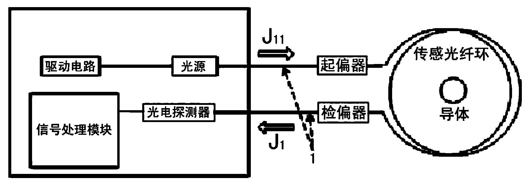
[0051] Since the discharge pulse energy is small and has certain randomness, and some interference signals are many times larger than the discharge signal of the device itself, this seriously affects the sensitivity of the test and the reliability of the detection, so it is necessary to develop a high-performance sensor. The corresponding Jones matrix is ​​deduced for the optical device involved in the present invention, and the mathematical model of the optical fiber current sensor is established. The partial discharge current signal has the characteristics of wide frequency distribution and weak amplitude. It is necessary to develop a broadband high-frequency fibe...


PUM


Abstract

The invention discloses a capacitive equipment partial discharge detection method based on an optical fiber current sensor. The capacitive equipment partial discharge detection method based on the optical fiber current sensor mainly comprises the following steps: establishing a mathematical model of the optical fiber current sensor; designing the structure of the optical fiber current sensor; analyzing and testing the performance of the optical fiber current sensor; testing a local discharge experiment system. According to the capacitive equipment partial discharge detection method based on the optical fiber current sensor, which is disclosed by the invention, the defects of poor antijamming capability, low reliability, small applicable range and the like in the prior art can be overcome, and the advantages of good antijamming capability, high reliability and big applicable range can be realized.

Description

technical field [0001] The invention relates to the technical field of power monitoring, in particular to a method for detecting partial discharge of capacitive equipment based on an optical fiber current sensor. Background technique [0002] With the development of the national economy, the requirements for the reliable operation of the power system are getting higher and higher. Electrical equipment is the basic component of the power system. Once an accident occurs, it will not only affect adjacent equipment, but also cause heavy economic losses to users. A large amount of data shows that insulation failure is the main cause of electrical equipment failure, and partial discharge is the main cause of insulation failure. Due to partial discharge caused by insulation defects, the long-term breakdown voltage of the dielectric is often less than the short-term breakdown voltage. A fraction, therefore, partial discharge has been paid much attention as a major factor of insulat...

Claims


Application Information

Patent Timeline
IPC IPC(8): G01R31/12G06F19/00
Inventor 毛光辉李世伟王锋杨贤明张振胡春江温定筠孙亚明赵景峰李睿
Owner STATE GRID CORP OF CHINA
Why Eureka
Try Eureka