
A particle size distribution measurement method based on shifrin transformation

A technology of particle size distribution and measurement method, applied in measurement devices, particle size analysis, particle and sedimentation analysis, etc., can solve problems such as inability to adapt to various situations and indistinguishable, and achieve the best inversion effect and good noise effect.

Inactive Publication Date: 2015-10-21
NANTONG UNIVERSITY
View PDF3 Cites 0 Cited by
  • Summary
  • Abstract
  • Description
  • Claims
  • Application Information

AI Technical Summary

Problems solved by technology

[0004] In the process of continuous research by the inventors, it was found that the above-mentioned improvement scheme can better solve the problem of noise in some cases, but due to the solidification of compensation factors, it cannot adapt to various situations in actual measurement, such as when there are When there are two relatively close distribution peaks, the above improved scheme cannot clearly distinguish the two in the inversion spectrum, thus limiting the application of the scheme to a certain extent

Method used


Image

  • A particle size distribution measurement method based on shifrin transformation
  • A particle size distribution measurement method based on shifrin transformation
  • A particle size distribution measurement method based on shifrin transformation

Examples


Embodiment 1

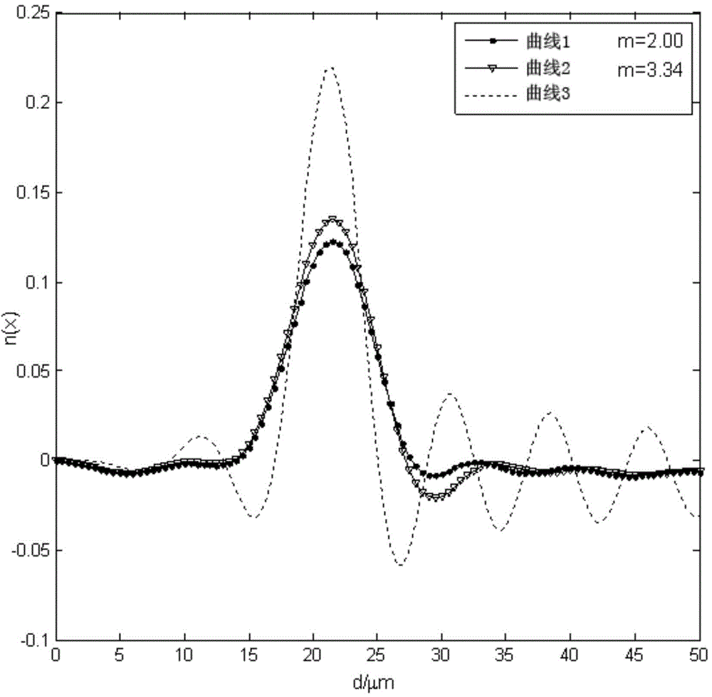
[0033] The present embodiment is based on the particle size distribution measurement method of shifrin transformation, and the steps are as follows:

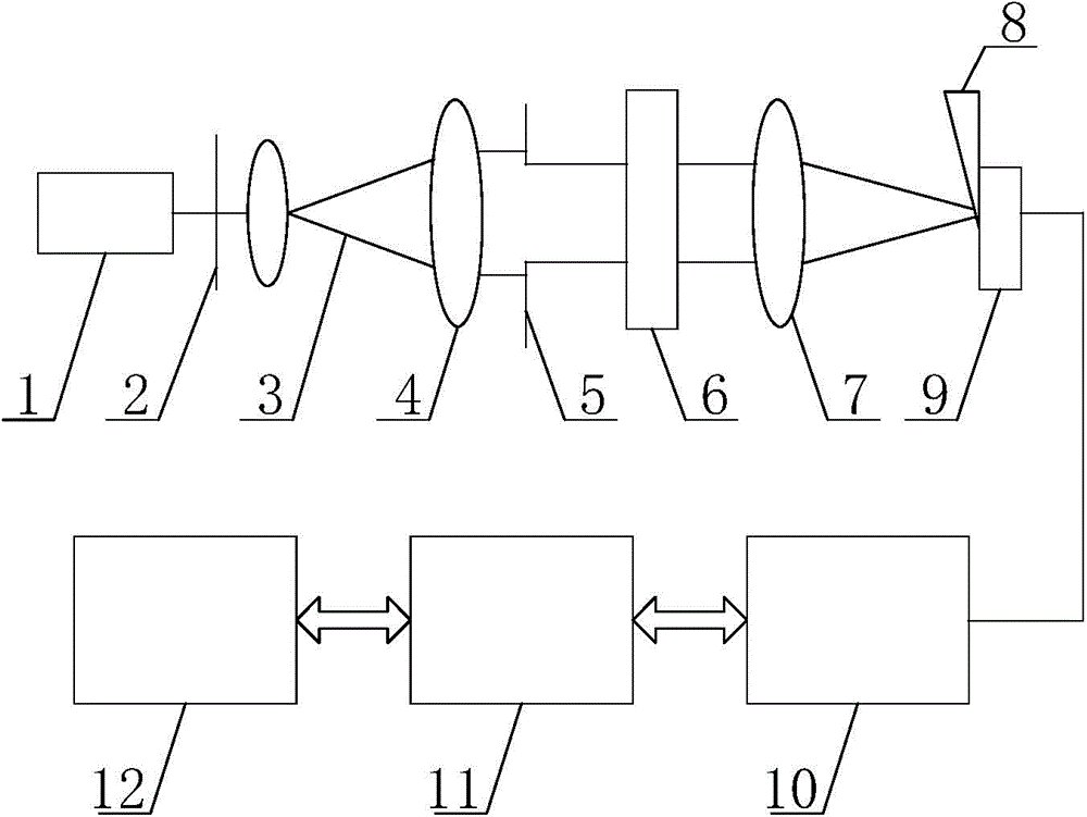
[0034] Step 1. Set the suspension of standard particle latex balls (produced by Beijing Institute of Chemical Industry and Metallurgy) in the sample box, specifically, suspend the sample of GBW(E)120006 (nominal mass peak particle size 20.46±0.4um) in pure water A unimodal distribution particle group is made in the sample box, and the sample box containing the aforementioned sample to be tested is installed in place;

[0035] Step 2. Turn on the laser. The light emitted by the laser becomes parallel light after attenuation, filtering, beam expansion and collimation, and then the light beam with a moderate diameter is adjusted by the iris to enter the sample box, and a beam will be formed on the focal plane of the objective lens. The scattering spectrum of the particle population;

[0036] Step 3, adjust the attenuator, so that ...

Embodiment 2

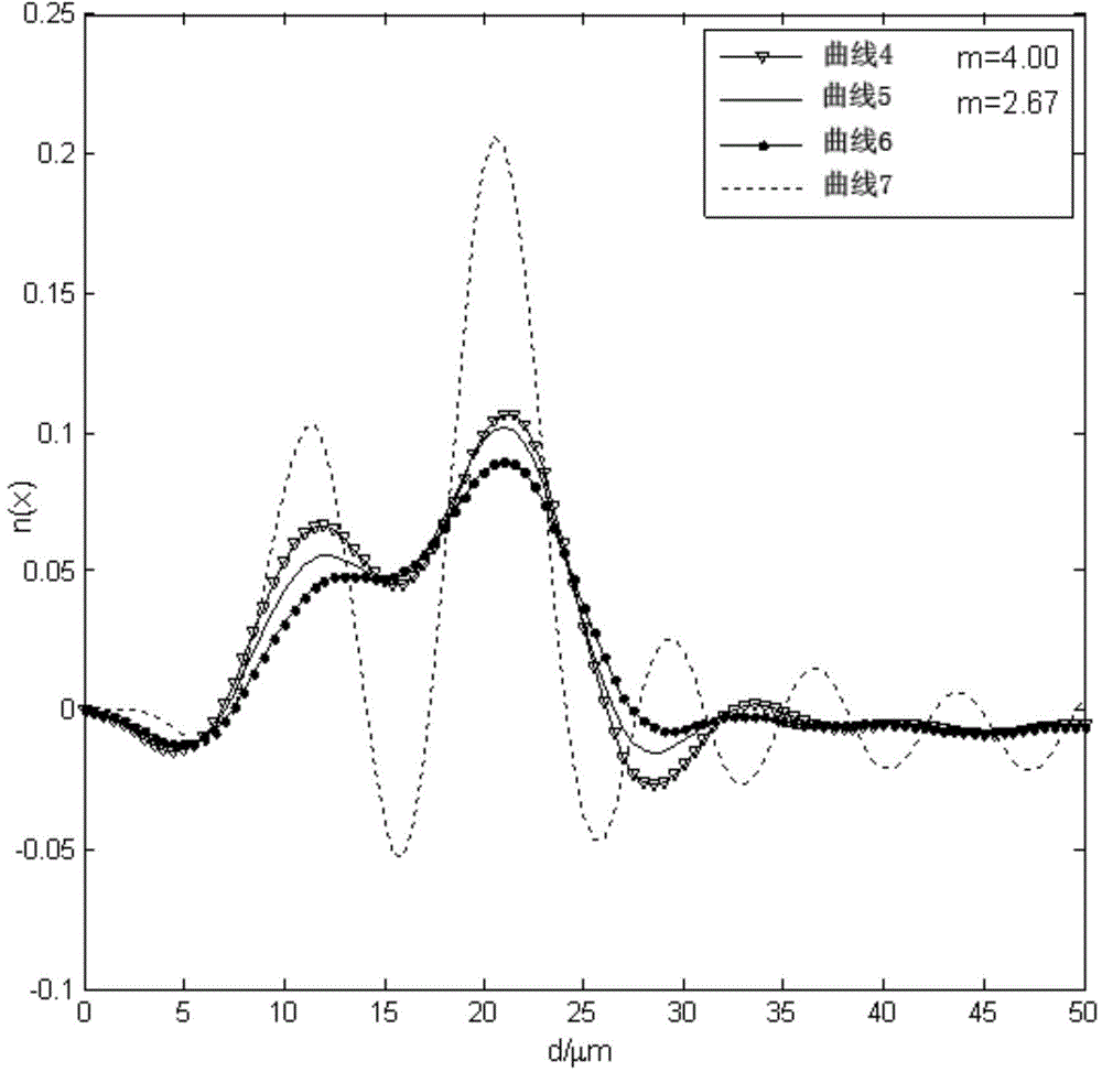
[0045] The steps of this embodiment can refer to the steps of Embodiment 1. The difference is: 1. The measurement object is a particle sample with bimodal distribution, specifically GBW (E) 120006 (nominal mass peak particle diameter 20.46 ± 0.4um) and GBW(E)120024 (nominal mass peak particle size 10.90±0.2um) is mixed to form a bimodal distribution particle group; 2. In step 6, if there is no clear distinction between adjacent distribution peaks after comparison, then Adjust the parameter m, and repeat step 5 until the ideal measurement result is obtained.

[0046] Finally, when the value of m is 4.00, the effect is the most ideal, the distribution peaks can be clearly distinguished, and the measurement accuracy is improved.

[0047] The particle size distribution of the particles obtained in this example can be found in image 3 Curve 4 in, as a control, image 3 The particle size distribution (curve 5) when m is 2.67, the particle size distribution (curve 7) obtained by t...


PUM

PropertyMeasurementUnit
diameteraaaaaaaaaa

Abstract

The invention relates to a shifrin transformation-based particle size distribution measurement method. A compensating factor with adjustable parameters is introduced in the process of inverting the particle size distribution, the noise of inversion under different parameters basically disappears, and the positions and number of distribution peaks are matched with those of nominal. The adjustable parameters are selected, and the defect that an existing method has a poor inversion effect under certain conditions can be obviously avoided. According to the method provided in the invention, the problem that the noise is large during laser particle size measurement is solved, and the adjustable parameters can be changed according to different conditions in actual measurement so as to achieve an optimal inversion measurement effect.

Description

technical field [0001] The invention relates to a method for measuring particle size distribution by Shifrin transformation, which belongs to the technical field of laser particle size measurement. Background technique [0002] The measurement of particle size distribution is a problem often encountered in engineering and scientific research. Optical methods have been widely used due to their non-contact sample and fast characteristics. At the end of the last century, due to the application of CCD components, the Shifrin inversion measurement based on laser diffraction The method has been developed, and the principle of the Shifrin inversion measurement method can be found in "A New Method for Measuring Particle Size Distribution Using Shifrin Transformation" published by the inventor in the "Journal of Nantong Institute of Technology" 2001-06. Although this method has the advantages of high precision and no need to predict information, it also has a very difficult problem, ...

Claims


Application Information

Patent Timeline
Patent Type & Authority Patents(China)
IPC IPC(8): G01N15/02
Inventor 戴兵袁银男钱鹏杨宗岺韩月
Owner NANTONG UNIVERSITY
Learn More