
Casting construction mold for water-cooled column and water-cooled beam of heating furnace

A water-cooled column and water-cooled beam technology, which is applied in the direction of construction, building structure, formwork/formwork/work frame, etc., can solve the problems of high cost of steel mold production, easy deviation of water-cooled columns, and increased wooden squares, etc., to achieve improved The effects of pouring quality, elimination of quality hazards, and enhanced versatility

Active Publication Date: 2016-04-20
CHINA FIRST METALLURGICAL GROUP
View PDF7 Cites 0 Cited by
  • Summary
  • Abstract
  • Description
  • Claims
  • Application Information

AI Technical Summary

Problems solved by technology

The production cost of the steel mold is high (about 100,000 yuan for a set of molds), it is bulky and difficult to operate, and it is easy to rust; the wood mold is easy to operate, but the clamps commonly used in the construction industry take up space, which affects the transportation of materials during construction, and is reinforced with screws , it is necessary to increase the number of wooden squares and increase the construction cost
[0004] There are common problems in the previous steel molds and wooden molds: 1. The bottom of the water-cooled column is easy to deviate; 2. The joints of the tee molds are prone to pockmarks and exposed anchor nails; 3. The slope on the upper surface of the water-cooled beam, due to the ceramic The fiber mat has a certain degree of elasticity, and the castable will crack before it reaches the strength
4. The junction between the slope of the water-cooled beam and the straight section is not straight; 5. The thickness of the insulation layer on both sides of the water-cooled beam is uneven

Method used


Image

  • Casting construction mold for water-cooled column and water-cooled beam of heating furnace
  • Casting construction mold for water-cooled column and water-cooled beam of heating furnace
  • Casting construction mold for water-cooled column and water-cooled beam of heating furnace

Examples


Embodiment Construction

[0031] In order to better understand the present invention, the technical solutions of the present invention will be further described below with reference to the embodiments and accompanying drawings.

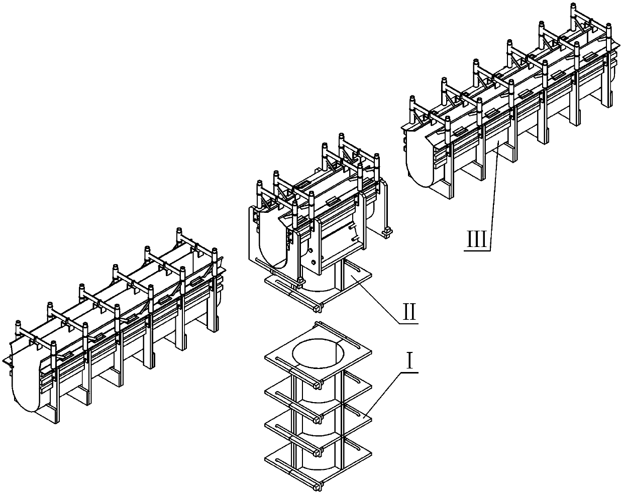
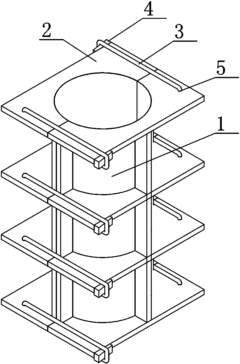
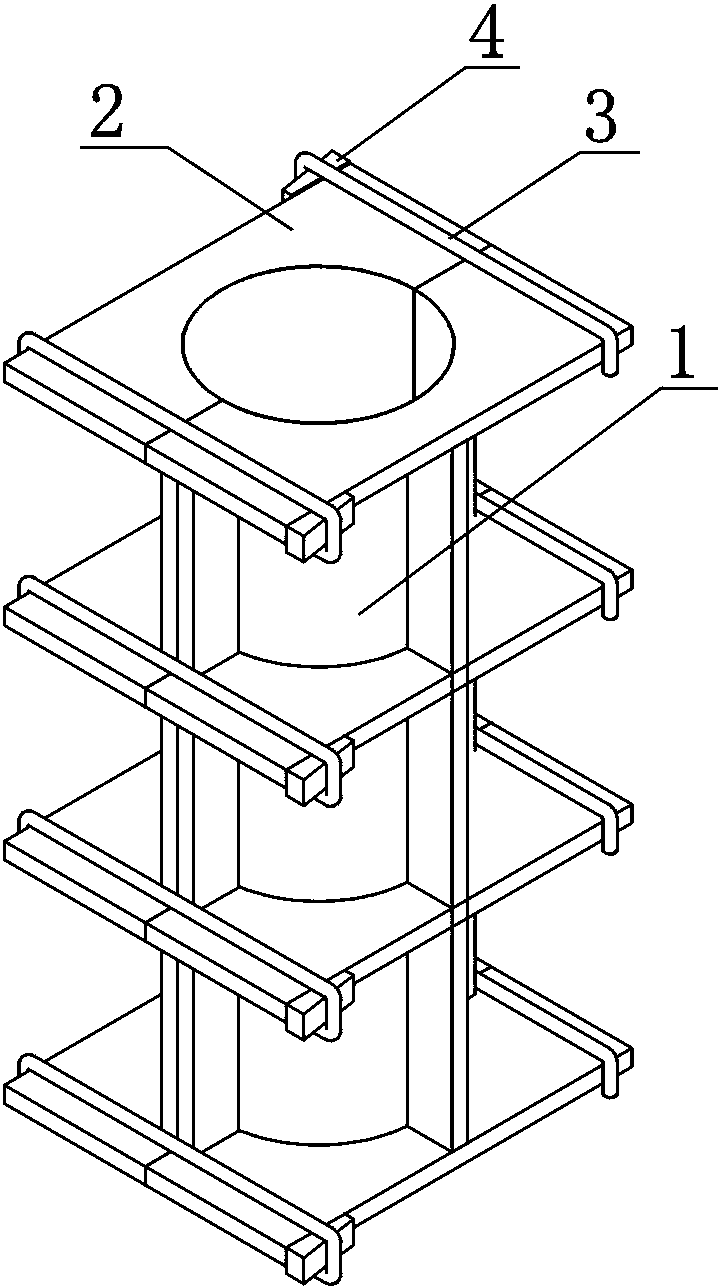
[0032] like Figure 1-12 As shown, a heating furnace water-cooled column and water-cooled beam casting construction mold, which includes a water-cooled column mold I, a three-way mold II and a water-cooled beam mold III, such as figure 2 , 3 As shown, the water-cooled column mold I is mainly assembled from a pair of water-cooled column half-moulds 1. The outer surface of the water-cooled column half-mould 1 is provided with reinforcing ribs in the axial direction, and a plurality of wooden rib plates 2 are evenly arranged in the circumferential direction. (The reinforcing rib is made of wood, and is combined with the wooden rib plate 2 to form a wooden frame), a pair of water-cooled column half-moulds 1 are fixed together by a locking device, and the locking device is fixedl...


PUM


Abstract

The invention relates to a casting construction mold for water cooling columns and water cooling beams of heating furnaces. The casting construction mold for water cooling columns and water cooling beams of heating furnaces comprises a water cooling column mold, a three-way mold and water cooling beam molds and is characterized in that: the water cooling column mold is mainly composed of a pair of water cooling column half molds which are assembled; the three-way mold is mainly composed of a pair of three-way half molds which are assembled; each water cooling beam mold comprises a U-shaped water cooling beam mold and a plurality of U-shaped wood jigs, and the U-shaped wood jigs are fixedly connected with the outer side of the U-shaped water cooling beam mold along the length direction. The mold can ensure that cast products of water cooling columns and water cooling beams can be accurately positioned, the structure of straight sections is straight, the phenomena of pitted surfaces and anchoring nail exposure do not exist at beam-column joints, water cooling beam slopes can be formed by casting in one step, the casting quality is increased, and potential quality hazards are eliminated.

Description

technical field [0001] The invention relates to a casting construction mould for a heating furnace water-cooled column and a water-cooled beam. Background technique [0002] The water-cooled beam of the heating furnace is divided into a movable beam and a fixed beam, and the steel ingot is transported from the feeding end of the heating furnace to the discharging end in a stepping method. The steel ingot is gradually heated, and impurities such as iron oxide on the surface of the steel ingot fall off and slide down the upper slope of the water-cooled beam. In the past construction of water-cooled beam pouring materials, the upper slope needs to be smeared twice, which is easy to delaminate and fall off after being heated; if it is formed by one-time pouring, the slope cannot be formed, so that the iron oxide cannot slide down, resulting in partial burnout of the steel ingot, which affects the rolling. quality. [0003] There are two types of water-cooled beam and column mo...

Claims


Application Information

Patent Timeline
Patent Type & Authority Patents(China)
IPC IPC(8): E04G13/00E04G13/02E04G13/04
Inventor 夏春徐超李国庆张伟山金国祥田红云王晶琼范存乐李胜涛王清春
Owner CHINA FIRST METALLURGICAL GROUP
Learn More