
Microfluidic chip based on pneumatic micro pumps and micro mixer

A technology of microfluidic chips and pneumatic micropumps, which is applied in the direction of instruments, laboratory appliances, chemical instruments and methods, etc., can solve the problems of multiple reagents, time, consumption, etc., and achieve the effect of efficient mixing and accurate automatic liquid transportation

Inactive Publication Date: 2014-06-18
SHENYANG INST OF AUTOMATION - CHINESE ACAD OF SCI
View PDF4 Cites 31 Cited by
  • Summary
  • Abstract
  • Description
  • Claims
  • Application Information

AI Technical Summary

Problems solved by technology

[0005] Aiming at the above-mentioned problems of consuming more reagents and time in the transportation and mixing of fluids, a microfluidic chip based on a pneumatic micropump and a micromixer is provided, which can quickly and accurately realize the transportation and mixing of trace amounts of liquids. mixed control

Method used


Image

  • Microfluidic chip based on pneumatic micro pumps and micro mixer
  • Microfluidic chip based on pneumatic micro pumps and micro mixer
  • Microfluidic chip based on pneumatic micro pumps and micro mixer

Examples


Embodiment Construction

[0024] The present invention will be further described in detail below in conjunction with the accompanying drawings and embodiments.

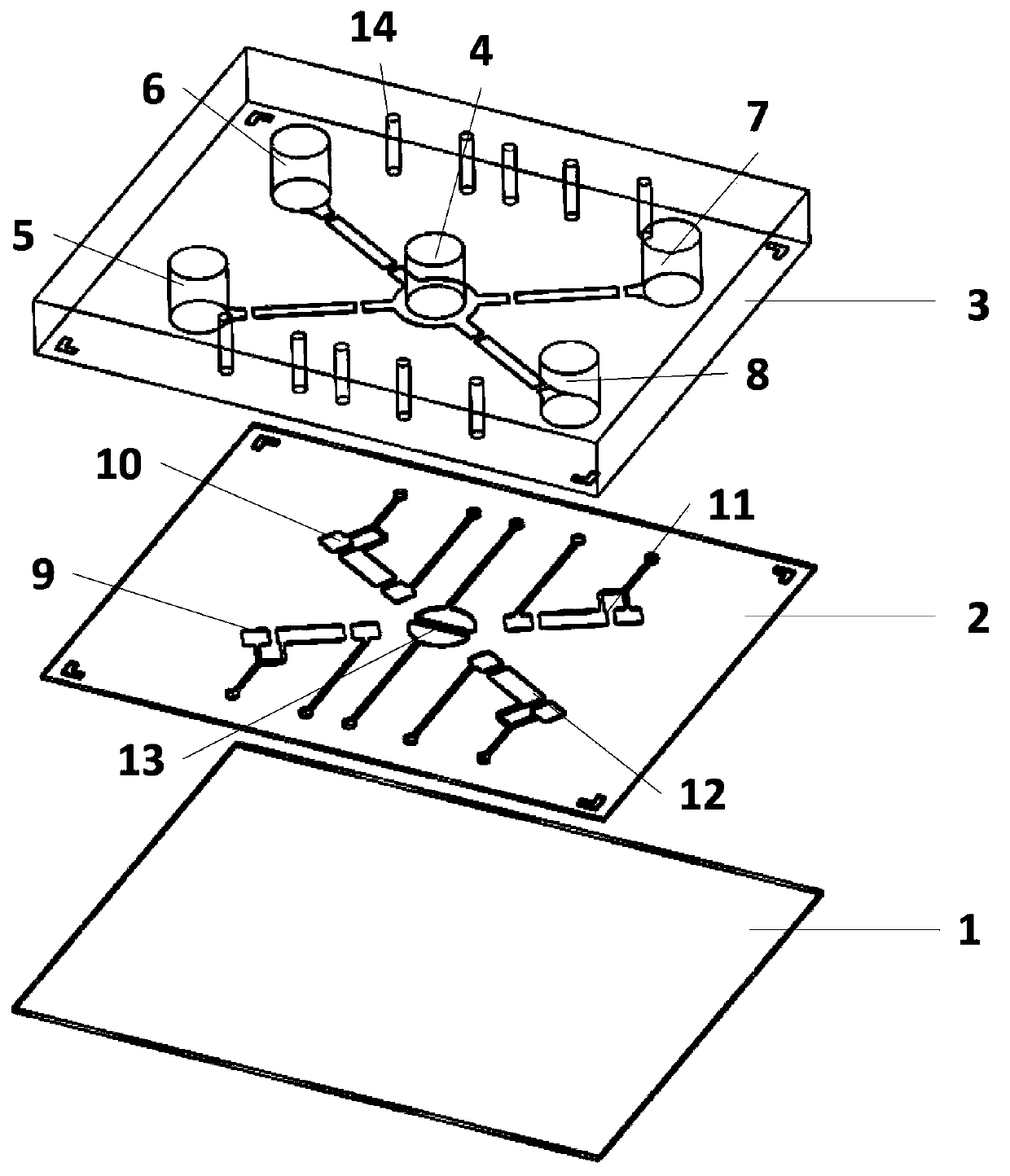
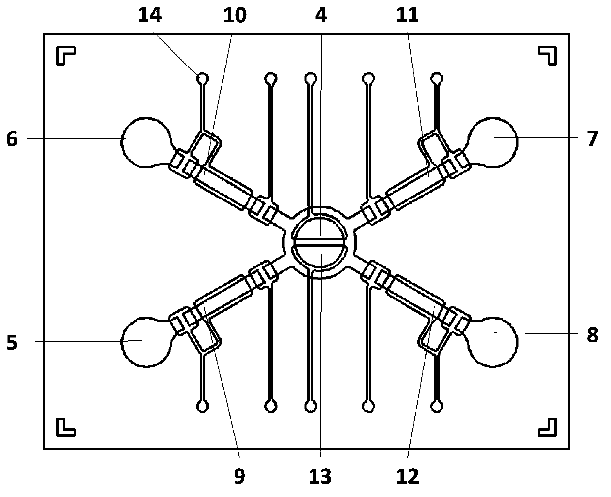
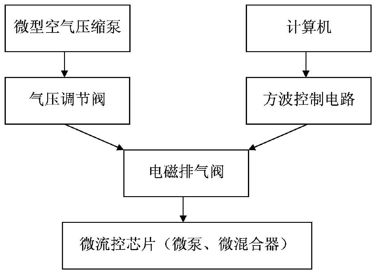
[0025] Such as figure 1 As shown, it is a schematic diagram of the three-layer structure decomposition of the microfluidic chip of the present invention. It is a microfluidic chip based on a pneumatic micropump and a micromixer. The microfluidic chip adopts a three-layer structure. Layer 2 and liquid flow layer 3; wherein, the lower surface of the gas driving layer 2 includes a micro-mixer 13 composed of an air chamber, and a plurality of pneumatic micro-pumps and gas passages are distributed around it; the liquid flow layer 3 includes a micro-mixing chamber 4 , a plurality of micro-reservoirs and the fluid channels connected thereto, the number and distribution position of the pneumatic micro-pumps correspond to the number and position of the fluid channels of the liquid flow layer 3 up and down; the additional pulse air pressure is controll...


PUM

PropertyMeasurementUnit
Thickness dimensionaaaaaaaaaa

Abstract

The invention discloses a microfluidic chip based on pneumatic micro pumps and a micro mixer. The microfluidic chip adopts a three-layer structure, a bottom layer is a glass substrate, and a gas drive layer and a liquid flow layer which are made of elastic materials are successively arranged on the substrate; the liquid flow layer comprises a micro mixing chamber, a plurality of micro liquid storage tanks and fluid channels, one end of each fluid channel is connected to the corresponding micro liquid storage tank, and the other end of each fluid channel is connected to the micro mixing chamber; the gas drive layer comprises the micro mixer, a plurality of pneumatic micro pumps and gas channels; externally-added pulse gas pressure is orderly controlled to enter the gas drive layer by an electromagnetic exhaust valve, the pneumatic micro pumps made of the elastic materials and the micro mixer are allowed to work, multiple channels of different solutions are orderly injected into the micro mixing chamber for mixing, so as to realize a purposeful trace chemical reaction. The microfluidic chip can be used for rapid, convenient and accurate realization of automated liquid transport and efficient mixing of a trace liquid, and has important practical significance.

Description

technical field [0001] The invention relates to a microfluidic chip, in particular to a microfluidic chip based on a pneumatic micropump and a micromixer, which realizes the control of transport and mixing of trace liquids. Background technique [0002] Microfluidic chip technology was developed in the field of analytical chemistry in the 1990s. It takes life science as the main research object and integrates the functions of the entire laboratory, including sample pretreatment, reaction, separation, and detection, on the microchip. Analysis speed has been greatly improved. The microfluidic chip has micron-scale structures and components, and is the main platform for the realization of microfluidic technology. It is also a hot field in the development of micro-total analysis systems. It has extremely wide applicability in life sciences, especially in the field of lab-on-a-chip. and important application prospects. [0003] The transportation and mixing of fluids are essent...

Claims


Application Information

Patent Timeline
IPC IPC(8): B01L3/00G01N35/00
Inventor 刘柱姚萍刘斌董再励童兆宏李国宾
Owner SHENYANG INST OF AUTOMATION - CHINESE ACAD OF SCI
Learn More