Self-moving corrector

A rectifier, self-moving technology, applied in the direction of conveyor objects, conveyors, transportation and packaging, etc., can solve the problems of inconvenient production, installation deviation, belt manufacturing and joint geometry not straight, etc., to achieve the effect of convenient installation

Inactive Publication Date: 2014-06-11
洛阳广盈机械设备有限公司
View PDF6 Cites 1 Cited by
  • Summary
  • Abstract
  • Description
  • Claims
  • Application Information

AI Technical Summary

Problems solved by technology

2. Rack manufacturing error and installation deviation
3. The quality of belt manufacturing and joints produces errors in geometric dimensions (not straight, uneven thickness)
4. Installation error of belt conveyor tensioning device
6. Roller manufacturing error and installation deviation
The mechanical deviation adjustment device is mainly the self-aligning roller, but because the belt conveyor is generally very harsh in industrial and mining, affected by dust and moisture, the slewing bearing of the self-aligning roller is easy to get stuck after a period of time, not only cannot adjust the deviation, but becomes "The source of deviation"; the hydraulic system is affected by the environment during the use of the hydraulic deviation adjustment device, which is prone to hydraulic system failures and hydraulic cylinder failures. The hydraulic deviation adjustment device fails and stops working, which brings great inconvenience to production.
[0006] It can be seen that the above-mentioned existing deviation adjustment device obviously still has inconvenience and defects in structure and use, and needs to be further improved urgently.

Method used


Image

  • Self-moving corrector
  • Self-moving corrector
  • Self-moving corrector

Examples


Embodiment Construction

[0033] In order to further explain the technical means and effects of the present invention to achieve the intended purpose of the invention, the specific implementation, structure, characteristics and features of the self-moving orthotic proposed according to the present invention will be described below in conjunction with the accompanying drawings and preferred embodiments. Efficacy, detailed as follows.

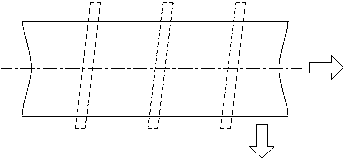
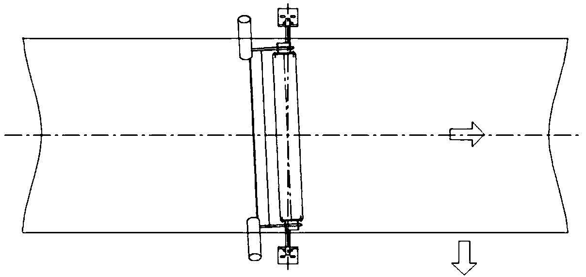
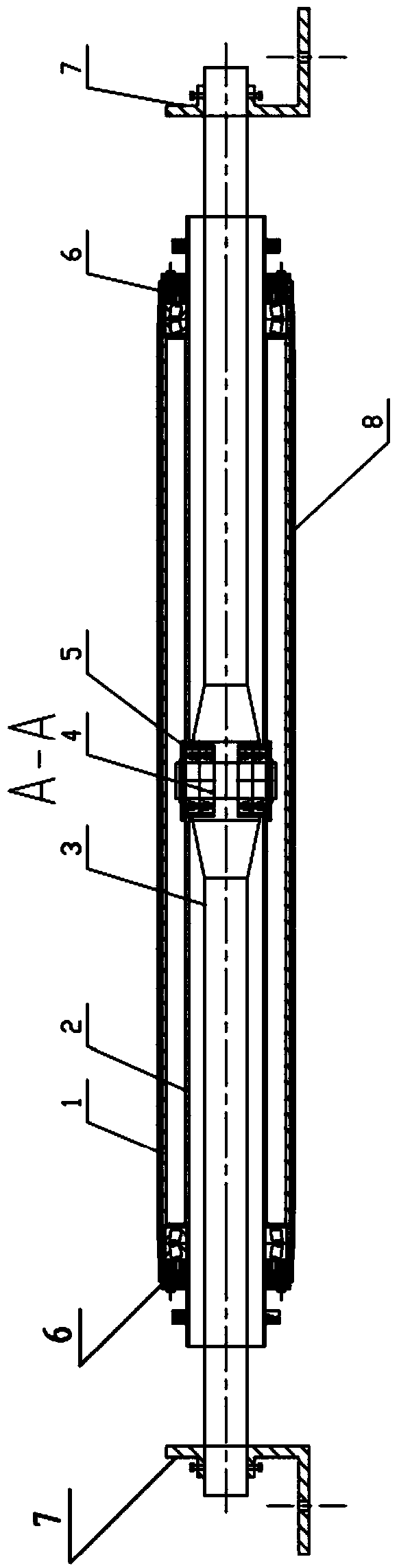
[0034] see figure 1 , figure 2 , image 3 , Figure 4 , figure 1 It is the force analysis diagram of the belt deviation of the self-moving corrector of the present invention. figure 2 It is a working force analysis diagram of the self-moving orthotic of the present invention. image 3 It is A-A sectional view of the self-moving orthotic of the present invention. Figure 4 It is a top view of the self-moving orthotic of the present invention.

[0035] The present invention proposes a self-moving straightener, comprising: a straightening outer cylinder 1, a straigh...


PUM


Abstract

The invention relates to a self-moving corrector. The self-moving corrector comprises an outer correction cylinder, an inner correction cylinder, self-moving oscillating shafts, a self-moving revolving shaft, a revolving seal assembly, sleeve seal assemblies, support frames, outer cylinder rubber coating, side vertical rolls, side roll stands and inner correction cylinder supports, wherein the self-moving oscillating shafts are installed at the middle parts of left and right support frames; the outer correction cylinder is sheathed with the inner correction cylinder through the sleeve seal assemblies; the sleeve seal assemblies are sheathed at the two outer ends of the inner correction cylinder and inner correction cylinder supports are arranged at the two outer ends of the inner correction cylinder; the inner correction cylinder is sheathed with the self-moving oscillating shafts through the self-moving revolving shaft and the revolving seal assembly. The self-moving corrector has the advantages that the self-moving corrector is not influenced by industrial mineral dust, water and crushed material environments and the belt deviation can be automatically corrected. A belt deviation correction method mainly takes the measure of installing a deviation adjusting device on a belt rack.

Description

technical field [0001] The invention relates to a self-moving straightening device, in particular to a self-moving straightening device of a deviation adjustment device. Background technique [0002] At present, belt conveyors have become the most important equipment for bulk material conveying systems in various industries, especially in industrial and mining enterprises such as thermal power plants, coal mines, steel mills, and mining factories. Phenomenon is one of the most common failures of belt conveyors. Deviations lead to scratches on the conveyor belt, tearing of the belt, scattering of conveyed materials, and damage to the rollers, which bury hidden dangers for production and safety, and even serious major safety incident. [0003] The main factors leading to deviation are as follows: 1. Roller processing and manufacturing errors and installation deviations. 2. Rack manufacturing errors and installation deviations. 3. The quality of belt manufacturing and joints...

Claims


Application Information

Patent Timeline
Patent Type & Authority Applications(China)
IPC IPC(8): B65G15/64B65G39/16
Inventor 孔凡军张宏才
Owner 洛阳广盈机械设备有限公司
Why Eureka
Try Eureka