
Simulation transformer lead detection method and system

A technology of transformer lead wire and detection system, which is applied in the directions of instruments, measuring electricity, measuring devices, etc., can solve the problem that the high-voltage metering cabinet cannot be trained.

Inactive Publication Date: 2014-06-04
NINGBO ELECTRIC POWER BUREA +1
View PDF6 Cites 0 Cited by
  • Summary
  • Abstract
  • Description
  • Claims
  • Application Information

AI Technical Summary

Problems solved by technology

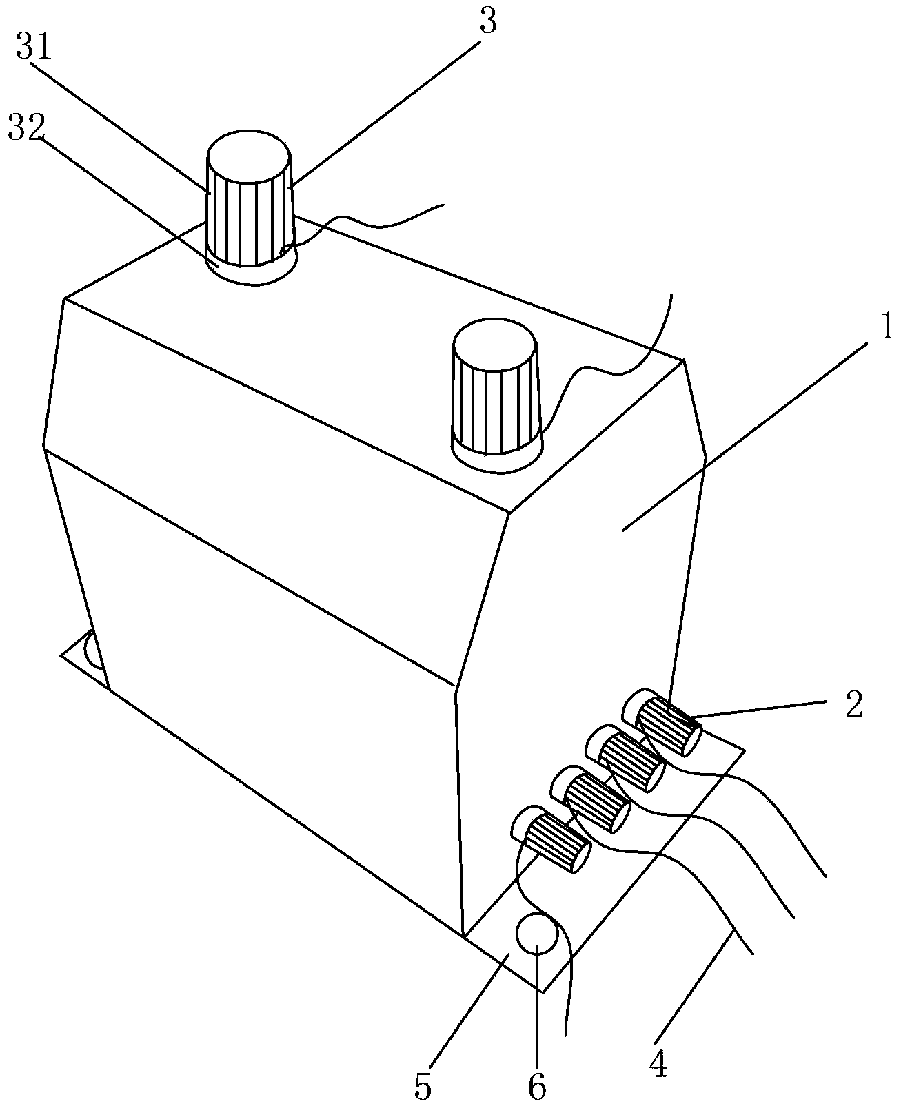
[0005] In view of this, the embodiment of the present application provides a simulation transformer lead detection method and system to solve the existing problem that the real high-voltage metering cabinet cannot be used for training

Method used


Image

  • Simulation transformer lead detection method and system
  • Simulation transformer lead detection method and system
  • Simulation transformer lead detection method and system

Examples


Embodiment 1

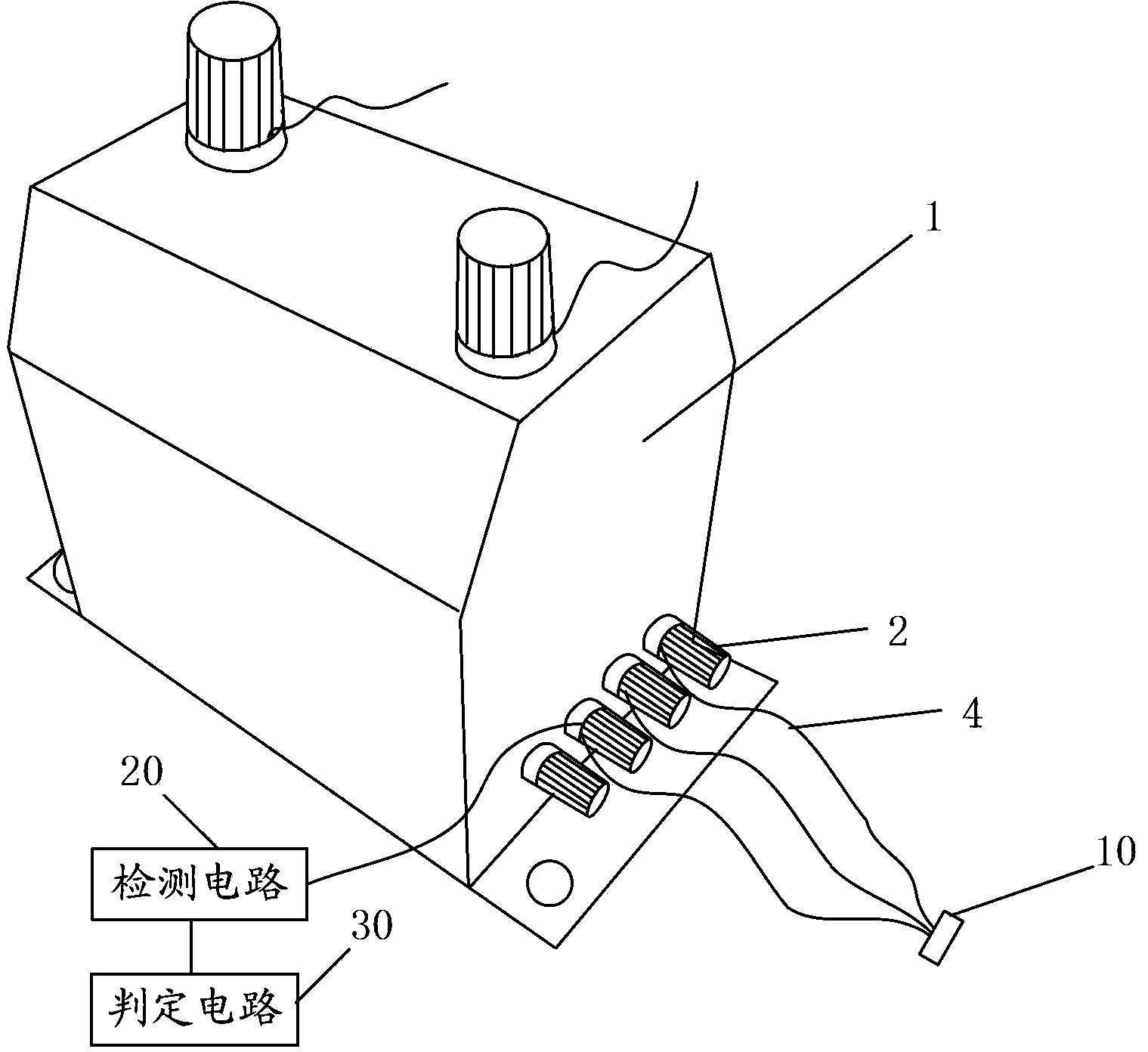
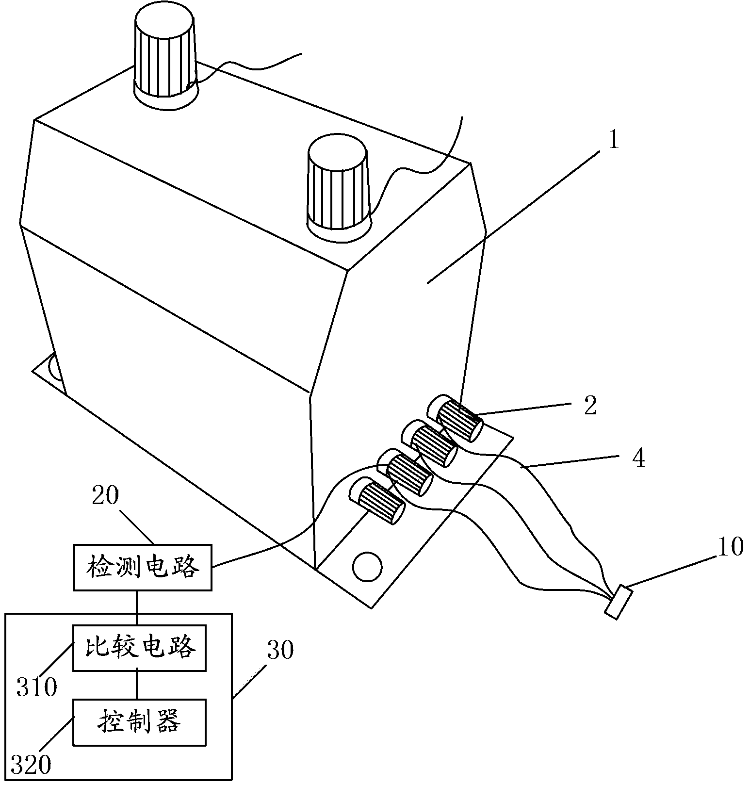
[0045] figure 2 It is a schematic structural diagram of a simulation transformer lead detection system provided in Embodiment 1 of the present application.

[0046] Such as figure 2 As shown, the system includes: a power supply device 10, a detection circuit 20 and a determination circuit 30, wherein:

[0047] The power supply device 10 is respectively connected to each lead wire 4 for outputting different electrical signals to each lead wire 4 . In the embodiment of the present application, the power supply device 10 may be a multi-pin socket. In the embodiment of the present application, the electrical signal may be a current signal or a voltage signal.

[0048] Multiple input terminals of the detection circuit 20 are respectively connected to multiple connection terminals for detecting electrical signals transmitted to the connection terminals via the lead wire 4 .

[0049] The determination circuit 30 is connected to a plurality of output ends of the detection circuit ...

Embodiment 2

[0056] Figure 5 It is a flow chart of a method for detecting lead wires of a simulated transformer provided in Embodiment 2 of the present application.

[0057] Such as Figure 5 As shown, the method includes:

[0058] S100: Inputting electrical signals to the lead wires connected to the connection terminals of the simulated transformer.

[0059] When inputting electrical signals, the multi-core socket can be used to simultaneously input electrical signals to multiple connecting terminals on the simulation transformer, and the electrical signals input by different connecting terminals are different. In the embodiment of the present application, the electrical signal may be a current signal or a voltage signal.

[0060] S200: Detect the electrical signal of the connection terminal at the position of the connection terminal.

[0061] The purpose of this solution is to detect the connection of the lead wires, so during the detection, the detection position is set at the posi...


PUM


Abstract

The application discloses a simulation transformer wire connection detection method and system. The system comprises a power supply device, a detection circuit and a decision circuit. The power supply device is connected with each lead separately for outputting different electrical signals to each lead. A plurality of input ends of the detection circuit are connected with a plurality of the connection terminals respectively for detecting the electrical signals transmitted to the connection terminals through the leads. The decision circuit is connected with a plurality of output ends of the detection circuit for comparing the detected electrical signals of the plurality of the connection terminal with a corresponding preset value and determining the connection condition of the leads on the plurality of the connection terminals according to the comparison result. According to the system, in the training process, trainers can simulate the wire connection process, and the existing problem that the training process cannot be performed through a real high-voltage metering cabinet can be solved.

Description

technical field [0001] The present application relates to the technical field of high-voltage measuring equipment, in particular to a method and system for detecting lead wires of simulated transformers. Background technique [0002] During normal power supply, the power supply company needs to install ammeters for high-voltage metering users. Meters are usually installed in substations or users’ power distribution rooms. Send a small current to the ammeter for measurement, and install and check the main working connecting wires of the ammeter. If the installation is wrong, it will cause accidents or double measurement errors, which will seriously affect the safety of electricity consumption and the settlement of electricity bills. Therefore, the power supply company actively carries out such training work internally to train employees to connect correctly. [0003] Since such training work is not allowed on site, the training is generally carried out in classrooms or spaci...

Claims


Application Information

Patent Timeline
IPC IPC(8): G09B23/18G01R31/02
Inventor 陈振虎龚明波刘沛立朱小武万真礼石琦
Owner NINGBO ELECTRIC POWER BUREA
Learn More