
Method for embedding optical fiber sensors in aircraft cabin

An optical fiber sensor and pre-embedded optical fiber technology, which is applied in the testing of machines/structural components, instruments, optical instruments, etc., can solve the problems that are not involved, and achieve the effect of easy layout, meeting measurement accuracy requirements, and high reliability.

Active Publication Date: 2014-06-04
BEIJING AEROSPACE TIMES OPTICAL ELECTRONICS TECH
View PDF13 Cites 9 Cited by
  • Summary
  • Abstract
  • Description
  • Claims
  • Application Information

AI Technical Summary

Problems solved by technology

But it does not involve specific engineering applications, such as the method of realizing the fiber optic smart structure of the aircraft cabin

Method used


Image

  • Method for embedding optical fiber sensors in aircraft cabin
  • Method for embedding optical fiber sensors in aircraft cabin

Examples


Embodiment Construction

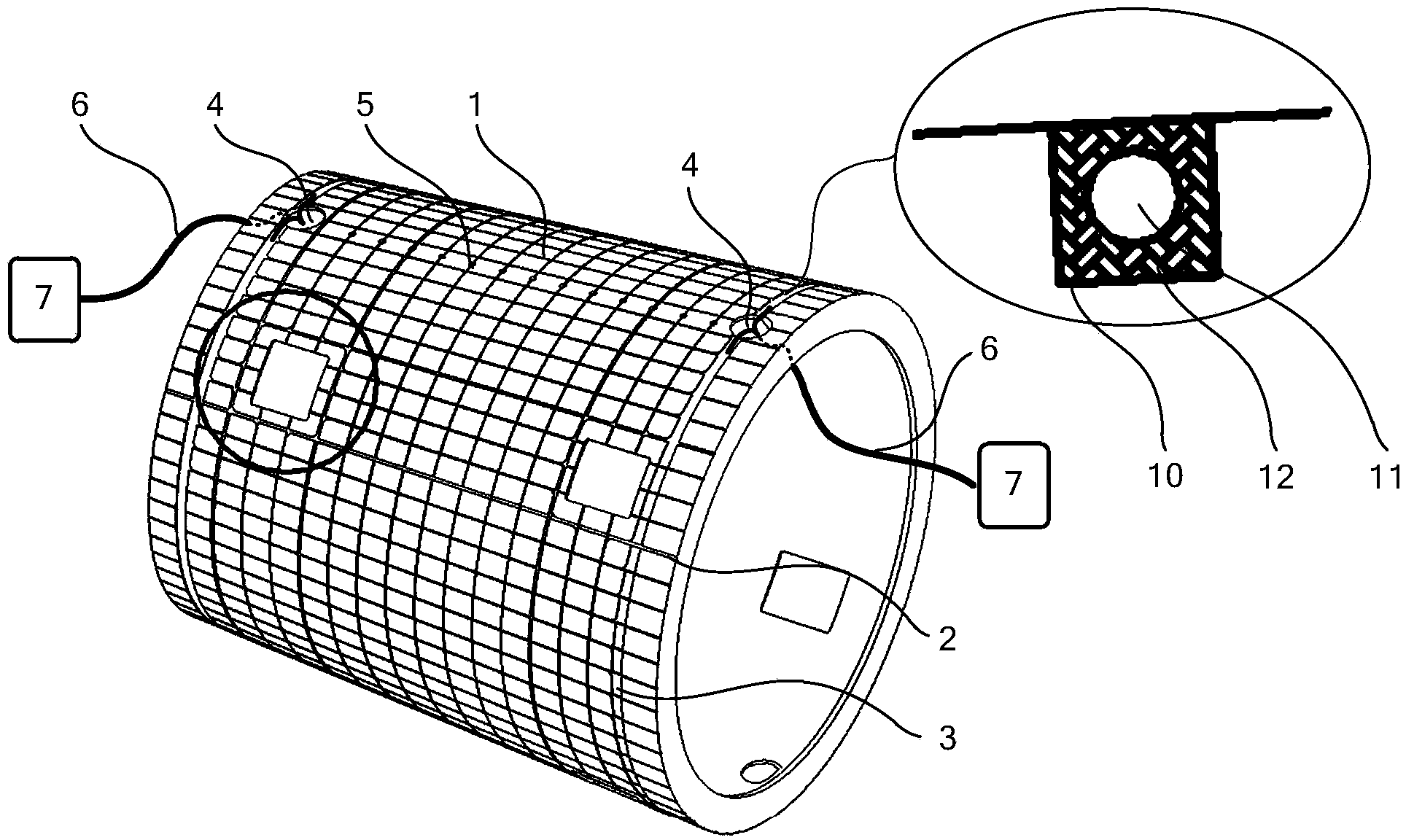
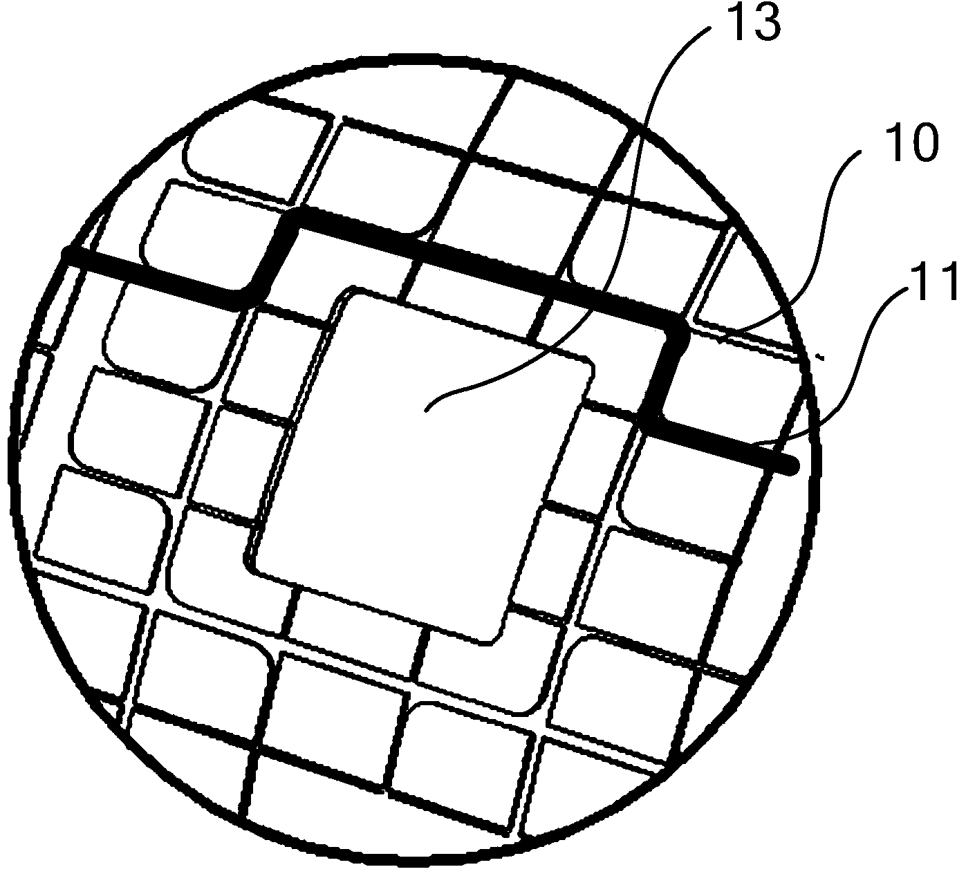
[0020] Such as figure 1 As shown, at first, during the structural processing of the aircraft cabin body 1, the longitude optical fiber groove 2, the latitude optical fiber groove 3, the longitude entry hole 4, and the latitude entry hole 5 are pre-set. Wherein, the longitude cabin entry holes 4 are located at both ends of the aircraft cabin body 1 structure, and the latitude cabin entry holes 5 are scattered and independently opened on the aircraft cabin body 1 structure circumference.

[0021] Put the longitude or latitude optical fiber sensors 11 into the corresponding longitude or latitude optical fiber grooves 10 sequentially, and fill and fix them with adhesive 12 . The longitude optical fiber sensors 11 that are about to enter the cabin at different positions can be collected at the latitude optical fiber grooves 3 at both ends, and guided to the corresponding longitude entry holes 4; after entering the cabin, the multi-channel longitude optical fiber sensors 11 are coll...


PUM

PropertyMeasurementUnit
Elastic modulusaaaaaaaaaa

Abstract

Disclosed is a method for embedding optical fiber sensors in an aircraft cabin. A plurality of longitudinal grooves and a plurality of transverse grooves are formed in the surface of the aircraft cabin in advance, longitudinal cabin inlets are reserved in the two ends of the aircraft cabin, transverse cabin inlets corresponding to the transverse grooves one to one are formed in the circumference of the aircraft cabin, the multi-path optical fiber sensors are distributed in the multiple longitudinal grooves and the transverse grooves, the grooves are filled with glue and fixed, and then the optical fiber sensors can be embedded in the surface of the aircraft cabin. The multi-path optical fiber sensors pass through the corresponding longitudinal cabin inlets and the transverse cabin inlets, then enter the aircraft cabin, are gathered at the two ends of the cabin to form optical fiber bundles, are integrated to an optical fiber connector and then are connected with an information collection device or communicated with an adjacent cabin. By the method, the optical fiber sensors can be embedded in the surface of a single-cabin or multi-cabin butt joint type aircraft, an optical fiber sensing and detecting network is achieved, the mechanical property and damage situations of the aircraft cabin can be monitored comprehensively, and the method has the advantages that reliability is high and operation is easy.

Description

technical field [0001] The invention relates to a method for pre-embedding an optical fiber sensor in an aircraft cabin, which realizes the purpose of an aircraft optical fiber intelligent structure, and is used for state monitoring and damage detection of the aircraft cabin structure. Background technique [0002] The intelligent structure is to embed or paste sensors in the substrate, so that it can perceive its own actual state, and realize various functions such as self-detection, self-diagnosis, self-monitoring, self-repair and self-adaptation under dynamic or online conditions. Its research began in the 1980s. The US government first proposed to carry out research in this area, and then other developed countries and regions in the world have successively carried out research on intelligent structures. In the 1990s, its potential application value in the military and civilian fields has attracted great attention, and the research on intelligent structures is unprecedent...

Claims


Application Information

Patent Timeline
IPC IPC(8): G01M11/08
Inventor 王巍单联洁杨勇田凌菲盖永辉崔留住张东旭胡常青王宇
Owner BEIJING AEROSPACE TIMES OPTICAL ELECTRONICS TECH
Learn More