
Combined regenerated lead oxygen-enriched three-blowing energy-saving smelting furnace

A regenerated lead, assembled technology, applied in furnaces, furnace components, energy efficiency improvement and other directions, can solve the problems of poor stirring effect of the melt in the furnace pool, high energy consumption, uneven feeding, etc., to improve energy utilization Efficiency, improve heat utilization efficiency, increase the effect of preheating effect

Inactive Publication Date: 2014-06-04
ANHUI HUAXIN LEAD IND GROUP +1
View PDF2 Cites 3 Cited by
  • Summary
  • Abstract
  • Description
  • Claims
  • Application Information

AI Technical Summary

Problems solved by technology

In the past two years, a new side-blowing smelting furnace has been further improved in terms of energy saving and reduction of lead content in waste slag, but there are still several problems that need to be improved urgently: first, the disturbance and stirring effect of the melt in the furnace pool is not good; The reason is that the fixed feeding port causes uneven feeding, the closed molten pool cannot be stirred directly, and the reduction is difficult to complete completely. To increase the reduction degree, excessive addition of reducing agent is forced, resulting in serious waste of reducing agent; the third is that the oxygen blown into the molten pool is mixed with gas The proportion of gas is difficult to control scientifically. If the proportion of oxygen is too high, it will cause excessive oxidation, which will affect the reduction of the melt and increase the amount of reduction, resulting in high energy consumption. The proportion of oxygen is low, resulting in endless combustion of gas and waste of energy. Fourth, the heat-resistant material of the furnace is corroded. The damage is fast, and the furnace body is built at one time, so it is inconvenient to disassemble and the maintenance cost is high

Method used


Image

  • Combined regenerated lead oxygen-enriched three-blowing energy-saving smelting furnace
  • Combined regenerated lead oxygen-enriched three-blowing energy-saving smelting furnace

Examples


Embodiment Construction

[0021] Below by specific implementation, in conjunction with accompanying drawing, the present invention will be further described:

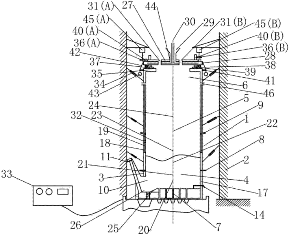
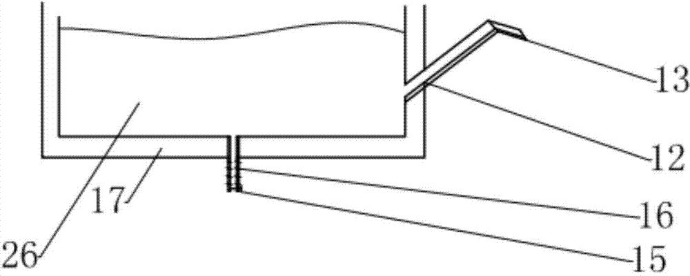
[0022] see figure 1 and figure 2 , an assembled regenerated lead oxygen-enriched three-blowing energy-saving smelting furnace. The furnace body 1 is vertically arranged. The furnace body 1 is divided into three parts: the lower section, the middle section and the upper section. The lower section is the smelting zone 4, and the lower section is from bottom to top. The upper part is further divided into static zone 20, bubbling zone 21 and reduction zone 22; the middle part is the waste heat utilization zone 5, the lower half of the waste heat utilization zone is the secondary combustion zone 23, and the upper half of the waste heat utilization zone is the raw material preheating zone 24; The upper part is the smoke exhaust and feeding area 6, the three parts of the furnace body are installed by hoisting and combination, the lower part is copper...


PUM


Abstract

The invention discloses a combined regenerated lead oxygen-enriched three-blowing energy-saving smelting furnace. A furnace body 1 is arranged vertically, the whole furnace body 1 is divided into a lower section, a middle section and an upper section, the lower section is a smelting area 4 and comprises a stationary area 20, a bubbling area 21, and a reduction area 22 from bottom to top, the middle section is a waste heat utilization area 5, the lower half part of the waste heat utilization area is a secondary combustion area 23, the upper half part of the waste heat utilization area is a raw material preheating area 24, the upper section is a smoke discharging and feeding area 6. The vertical furnace body is more convenient to fully use the waste heat of the offgas for preheating the raw material, so that the energy-saving effect is remarkably improved, the dosage of the reducing agent is reduced, and the content of lead in the slag is lowered. The novel furnace body adopts a metal water jacket component and is combined by segmental hoisting, thus being convenient to maintain, and greatly lowering the maintenance cost.

Description

technical field [0001] The invention relates to the technical field of metal smelting, more specifically to an assembled regenerated lead-enriched oxygen-enriched three-blowing energy-saving smelting furnace. Background technique [0002] With the intensification of the energy crisis, the importance of lead-acid batteries as energy storage carriers for new energy sources such as solar energy, wind energy, and nuclear energy has become increasingly apparent. However, lead mineral resources are facing depletion, and the recycling of secondary lead has become inevitable. Secondary lead is an emerging industry, and its smelting technology is in the exploratory stage. Its high energy consumption and high pollution issues have attracted much attention. National policies clearly require secondary lead smelting to ban various reverberatory furnaces that directly burn coal, speed up technological innovation, and promote energy conservation and emission reduction. At present, ...

Claims


Application Information

Patent Timeline
Patent Type & Authority Applications(China)
IPC IPC(8): C22B13/02C22B7/00F27D17/00
CPCY02P10/143Y02P10/25
Inventor 尚诚德
Owner ANHUI HUAXIN LEAD IND GROUP
Learn More