
Pulse signal conversion device for acquiring and synchronously triggering sound field measured data of ultrasonic phased array energy converter

A technology of ultrasonic phased array and pulse signal, which is applied in the direction of measuring device, measuring ultrasonic/sonic wave/infrasonic wave, pulse generation, etc. It can solve the problems of synchronous data acquisition and the difficulty of synchronous acquisition of phased array transducer sound field measurement data, etc. Achieve synchronous acquisition, improve anti-interference ability and save cost

Inactive Publication Date: 2014-05-28
BEIJING INSTITUTE OF TECHNOLOGYGY
View PDF4 Cites 8 Cited by
  • Summary
  • Abstract
  • Description
  • Claims
  • Application Information

AI Technical Summary

Problems solved by technology

[0003] However, ultrasonic phased array testing instruments used in conjunction with ultrasonic phased array transducers generally do not have a signal interface that receives a single pulse to trigger phased excitation and receive a single detection signal, and gives the phased array transducer sound field measurement data Simultaneous acquisition poses difficulties
Ultrasonic phased array detection instruments generally have an encoder signal interface to achieve the function of triggering detection at a specific position, but the encoder signal interface is two pulses, so it is necessary to develop a single pulse to two pulse signal conversion device to solve the problem. Data Synchronous Acquisition in Sound Field Measurement of Ultrasonic Phased Array Transducer

Method used


Image

  • Pulse signal conversion device for acquiring and synchronously triggering sound field measured data of ultrasonic phased array energy converter

Examples


Embodiment Construction

[0009] The specific circuit scheme of the present invention is described in detail below:

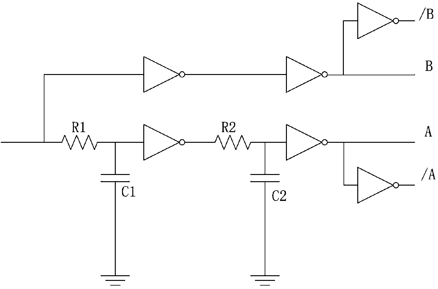
[0010] In the signal conversion device proposed by the present invention, the circuit composed of six inverters of the same model, two resistors with the same resistance value and two capacitors with the same capacitance value is as follows: figure 1 shown.

[0011] The invention completely uses independent components such as logic NOT gates, resistors, capacitors, etc., and realizes the delay of single-channel pulses through the RC response characteristics and the shaping characteristics of logic gate circuits, and then generates dual-channel pulse encoder analog signals with a certain phase difference . The number of output pulses is the same as the number of input pulses, no additional processing is required, and it has a shaping function for input rectangular pulses.

[0012] The present invention can only carry out equal pulse width delay to the pulse whose input pulse width is g...


PUM


Abstract

The invention provides a signal conversion device used in a sound field scanning system of an ultrasonic phased array energy converter. The signal conversion device has the function of converting a single-path pulse signal into a double-path difference encoder signal to finish the stimulation of the energy converter and the synchronous triggering of a data acquisition card. The signal conversion device utilizes independent elements including a logic inverter, a resistor, a capacitor and the like, RC (Remote Control) respond properties and reshaping properties of a logic gate circuit are used to realize the delaying of single-path pulses, so as to generate the double-path difference encoder signal with a certain phase difference. According to the signal conversion device, the pulse quantity of an encoder is the same as the quantity of input pulses and the widths of two paths of the pulses keep the same. An output signal is converted into a difference signal by using a phase inverter to improve the anti-jamming capability. With regard to the widths of the different input pulses or the frequencies of the different pulses, the signal conversion device can be adapted by simply adjusting capacitance and resistance parameters in the circuit. The device provided by the invention is small in volume, low in cost and easy to implement; functions can be expanded; the signal conversion device is applicable to the field of large-range pulse width conversion.

Description

1. Technical field: [0001] The present invention relates to a simple ultrasonic detection encoder trigger signal generation device, which can be applied to the ultrasonic sound field scanning system, which needs encoder trigger signal to trigger data collection, but the system does not use encoder, but uses single-channel pulse trigger The case of a stepper motor. The same device is also suitable for other similar applications. 2. Background technology: [0002] Ultrasonic testing technology has become an important part of the field of nondestructive testing. The performance of ultrasonic transducers in ultrasonic testing systems directly affects the reliability and credibility of testing. With the improvement of the quality requirements of industrial products, there are higher requirements for the precision and accuracy of ultrasonic testing. The sound field characteristic of an ultrasonic transducer is a relatively important performance parameter. For a longitudinal wave...

Claims


Application Information

Patent Timeline
IPC IPC(8): G01H17/00H03K3/013
Inventor 肖定国徐春广邵甲蒙任慧玲周世圆王巨琛
Owner BEIJING INSTITUTE OF TECHNOLOGYGY
Learn More