
Adjustable rotary kiln heat collection system and heat energy collection method

A heat energy collection, rotary kiln technology, applied in the direction of rotary drum furnace, waste heat treatment, lighting and heating equipment, etc., can solve the problems of low water cooling cycle efficiency, accelerated kiln body corrosion, poor heat exchange, etc., to achieve convenient disassembly and installation, The effect of improving energy efficiency and improving service life

Active Publication Date: 2014-05-28
宝利鑫新能源开发有限公司
View PDF8 Cites 9 Cited by
  • Summary
  • Abstract
  • Description
  • Claims
  • Application Information

AI Technical Summary

Problems solved by technology

[0002] At present, in the process production line produced by heating with large-scale rotary kiln, the temperature of the outer surface of the rotary kiln is relatively high, and the temperature can be as high as about 300°C. Most of the heat on the outer surface of the rotary kiln is not recycled and is lost to the atmosphere.
For the kiln body exposed to the atmosphere, it not only increases the fuel consumption during combustion, but also increases the production cost; at the same time, the outer surface of the high-temperature rotary kiln exposed to the atmosphere, under the erosion of rainwater, accelerates the corrosion of the kiln body and affects the kiln. body life
[0003] The kiln body heat collecting device of some existing production lines is an open type through water circulation, which can only collect heat on one side of the kiln body, and the water cooling cycle efficiency is low, and the heat exchange is poor, which affects the cooling effect of the kiln body surface. The surface temperature of the kiln body is too high, which affects normal production and operation. At the same time, the gap between the kiln body and the kiln body cannot be adjusted according to the needs. The collected water is not only at the bottom temperature, but also cannot adjust the water temperature. The heat recovery effect is poor, and the popularization and application are limited.

Method used


Image

  • Adjustable rotary kiln heat collection system and heat energy collection method
  • Adjustable rotary kiln heat collection system and heat energy collection method
  • Adjustable rotary kiln heat collection system and heat energy collection method

Examples


Embodiment 1

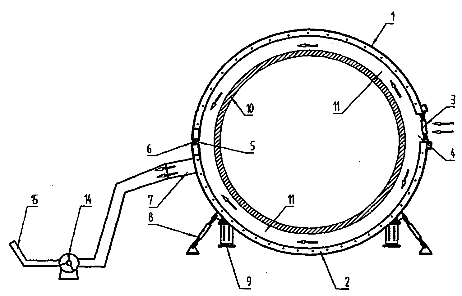
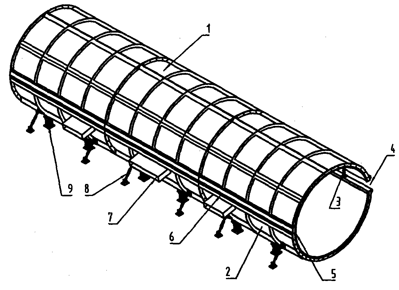
[0023] A semi-drum-shaped upper heat-collecting cover 1 is arranged above the semi-drum-shaped lower heat-collecting cover 2 to form a drum body heat-collecting cover, and a rotary kiln 10 is arranged inside the drum-shaped heat-collecting cover. Asbestos heat-resistant plates are arranged between 10, so that a sealed heat exchange channel 11 is formed between the drum body heat collecting cover and the rotary kiln 10; on one side of the drum body heat collecting cover, the upper heat collecting cover 1 and the lower heat collecting cover 2 Multiple sets of adjusting screw 3 are arranged between them, each group is at least 2, so that the cold air inlet 4 is formed between the upper heat collecting cover 1 and the lower heat collecting cover 2; 1 and the lower heat collecting cover 2 are provided with multiple sets of rotating hinge seats 6, each group is at least 2, an arc-shaped sealing plate 5 is arranged on the inner side between the upper heat collecting cover 1 and the lo...

Embodiment 2

[0025] The drum body heat collecting cover is divided into the whole drum body heat collecting cover and the combined drum body heat collecting cover, the combined drum body heat collecting cover is composed of at least two sections of the drum body heat collecting cover, the combined drum body An annular baffle 12 is arranged corresponding to the rotary kiln 10 between the adjacent two sections of the drum body heat collecting cover, and the annular baffle 12 makes each section of the drum body heat collecting cover and the rotary kiln 10 form an independent heat In the exchange channel 11, at least one hot air outlet 7 is arranged on the outer wall of the lower heat collecting cover 2 of each section of the drum body heat collecting cover.

Embodiment 3

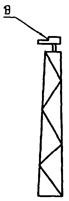
[0027] The cold air enters the heat exchange channel 11 between the drum heat collecting cover and the rotary kiln 10 from the cold air inlet 4, and the cold air exchanges heat with the outer surface of the rotary kiln 10 in the heat exchange channel 11, so that the outer surface of the rotary kiln 10 Cool down, at the same time, the cold air in the heat exchange channel 11 is heated, by adjusting the vertical support 9 of the drum body heat collecting cover, the diameter adjustment screw 8 and the adjustment screw 3, the space and cooling capacity of the heat exchange channel 11 can be changed. The intake air volume of the air makes the temperature of the hot gas in the heat exchange channel 11 reach the set standard value, and the hot gas is sucked into the pipeline 15 by the high-temperature fan 14 from the hot blast outlet 7 .


PUM


Abstract

The invention discloses an adjustable rotary kiln heat collection system and a heat energy collection method. The adjustable rotary kiln heat collection system is composed of an upper heat collection cover, a lower heat collection cover, an adjustable lead screw, a cold air inlet, an arc-shaped sealing plate, a rotating hinged support, a hot air outlet, a diameter adjustable lead screw, a vertical support, a rotary kiln, a heat exchange channel, an annular baffle, a barrel-shaped temperature measuring and scanning device, a high-temperature fan and a pipeline. The space of the heat exchange channel and the cold air inlet volume are changed by adjusting the barrel-shaped heat collection cover, the temperature of hot air in the heat exchange channel is made to reach a set standard value, and hot air is pumped into the pipeline through the high-temperature fan from the hot air outlet. Dispersed heat can be fully recycled, the space of the heat exchange channel and the cold air inlet volume are changed by adjusting the barrel-shaped heat collection covers, and the temperature of hot air in the heat exchange channel is made to reach the set standard value, so that the requirement for drying or heating other materials is met, combustor devices for heating other materials are omitted, and investment cost is reduced.

Description

technical field [0001] The invention relates to the technical field of heat collection on the outer surface of a large-scale rotary kiln, in particular to an adjustable rotary kiln for recovering heat from the outer surface of a rotary kiln in the production of cement clinker, a rotary kiln in the production of alumina, and a rotary kiln in the ceramic particle production industry. Kiln heat collection system and heat energy collection method. Background technique [0002] At present, in the process production line produced by heating with large-scale rotary kiln, the temperature of the outer surface of the rotary kiln is relatively high, and the temperature can be as high as about 300°C. Most of the heat on the outer surface of the rotary kiln is not recycled and is lost to the atmosphere. . For the kiln body exposed to the atmosphere, it not only increases the fuel consumption during combustion, but also increases the production cost; at the same time, the outer surface o...

Claims


Application Information

Patent Timeline
IPC IPC(8): F27D17/00F27B7/20F27B7/42
Inventor 李参军陈辉卢坡梁军伟罗扉皇涛
Owner 宝利鑫新能源开发有限公司
Learn More