
Repeating stud welding torch

A stud welding and continuous firing technology, applied in the characteristics of electrodes, welding equipment, arc welding equipment, etc., can solve the problems of low efficiency, high work intensity, and tired fingers of the operator.

Active Publication Date: 2014-05-28
青岛艾特尔电源科技有限公司
View PDF7 Cites 6 Cited by
  • Summary
  • Abstract
  • Description
  • Claims
  • Application Information

AI Technical Summary

Problems solved by technology

[0002] At present, stud welding torches are widely used in automobiles, shipbuilding, aviation, boilers, locomotives and other sheet metal industries. Due to the simple structure of the existing stud welding torches, each stud is inserted from the head of the welding torch by the operator. , the operator's fingers will be very tired, therefore, the efficiency is low and the labor intensity is high
In addition, the existing screw welding torch can only weld one welding stud at a time. When working on a large area, the efficiency is low and the work intensity is high

Method used


Image

  • Repeating stud welding torch
  • Repeating stud welding torch
  • Repeating stud welding torch

Examples


Embodiment Construction

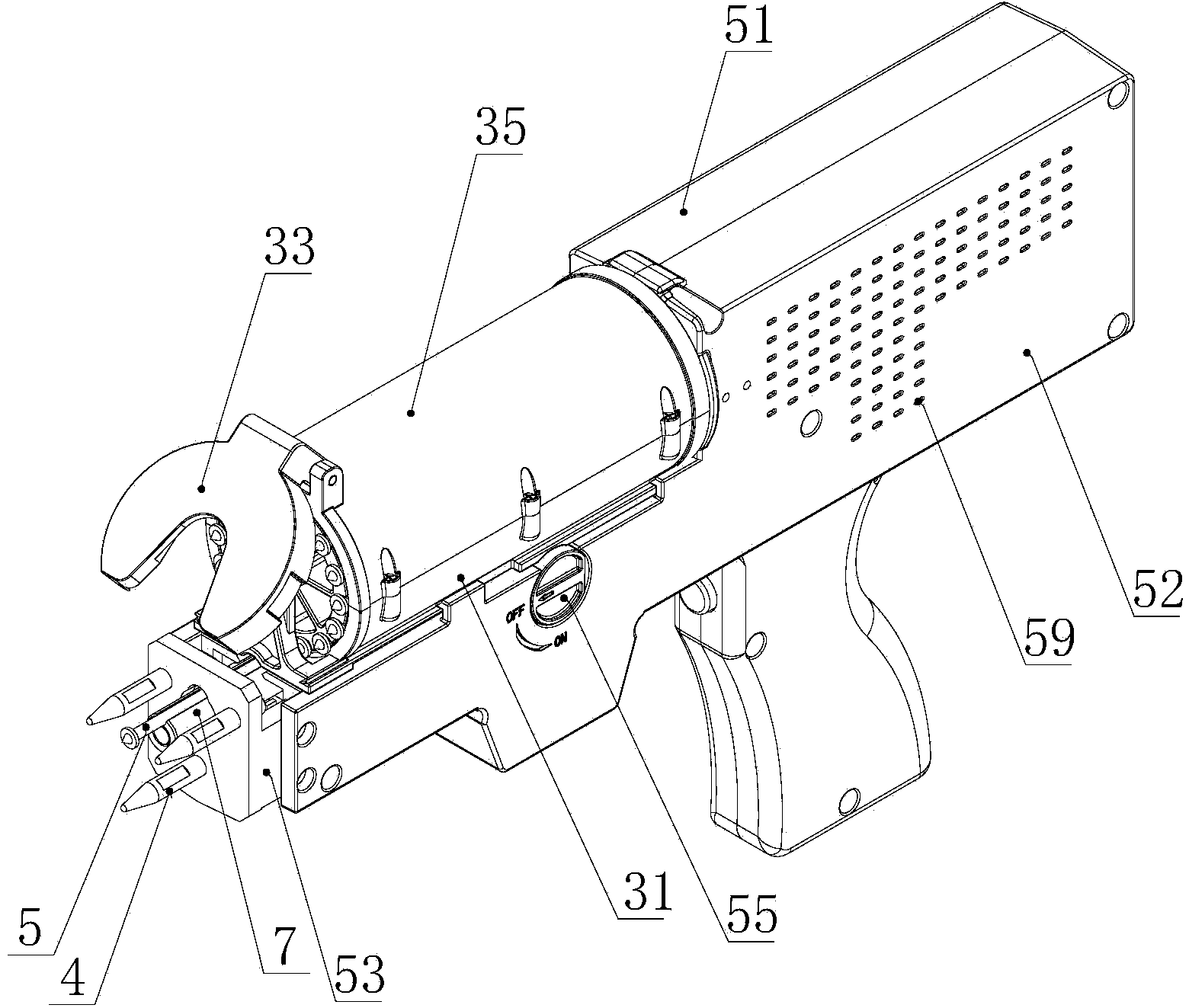
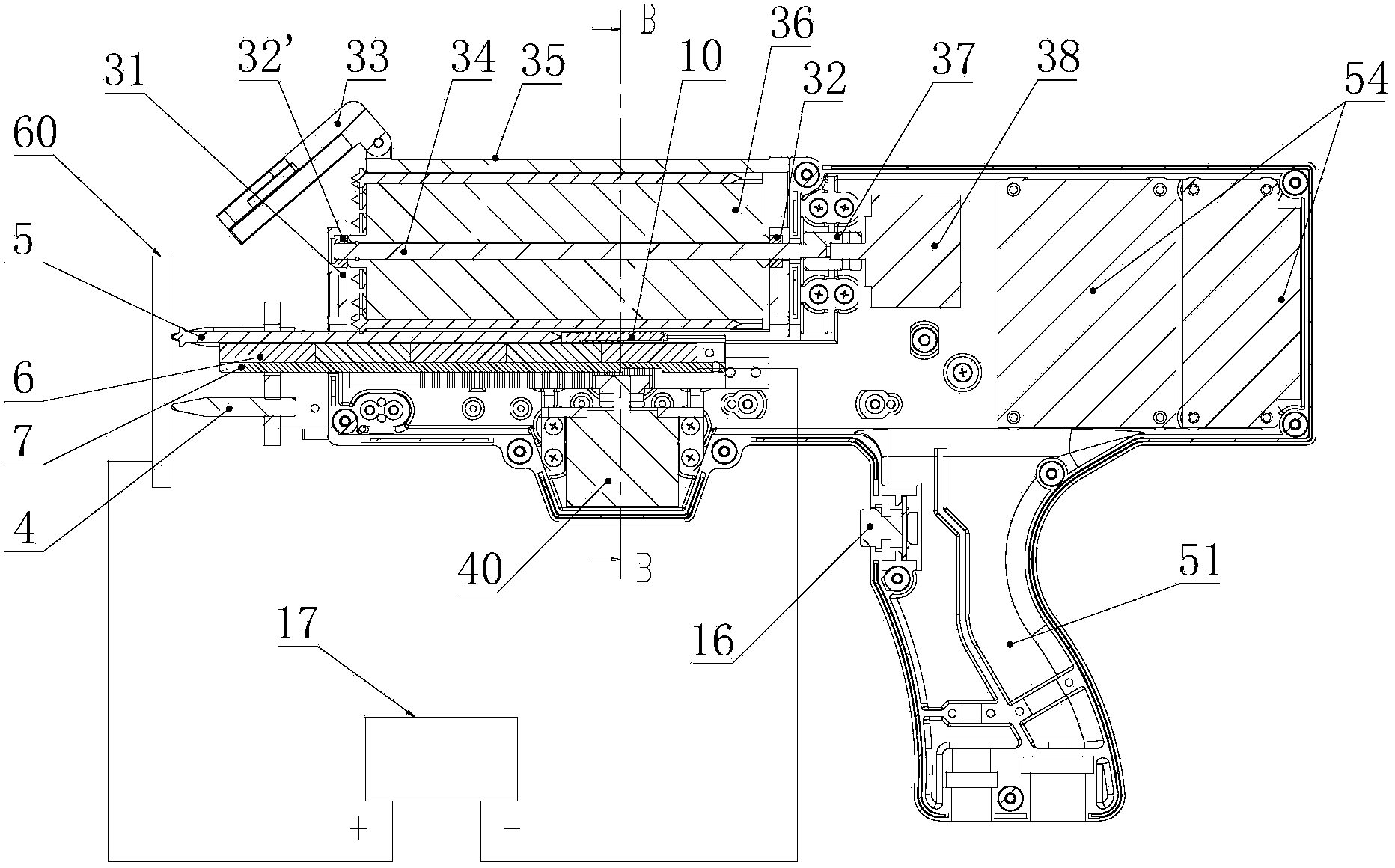
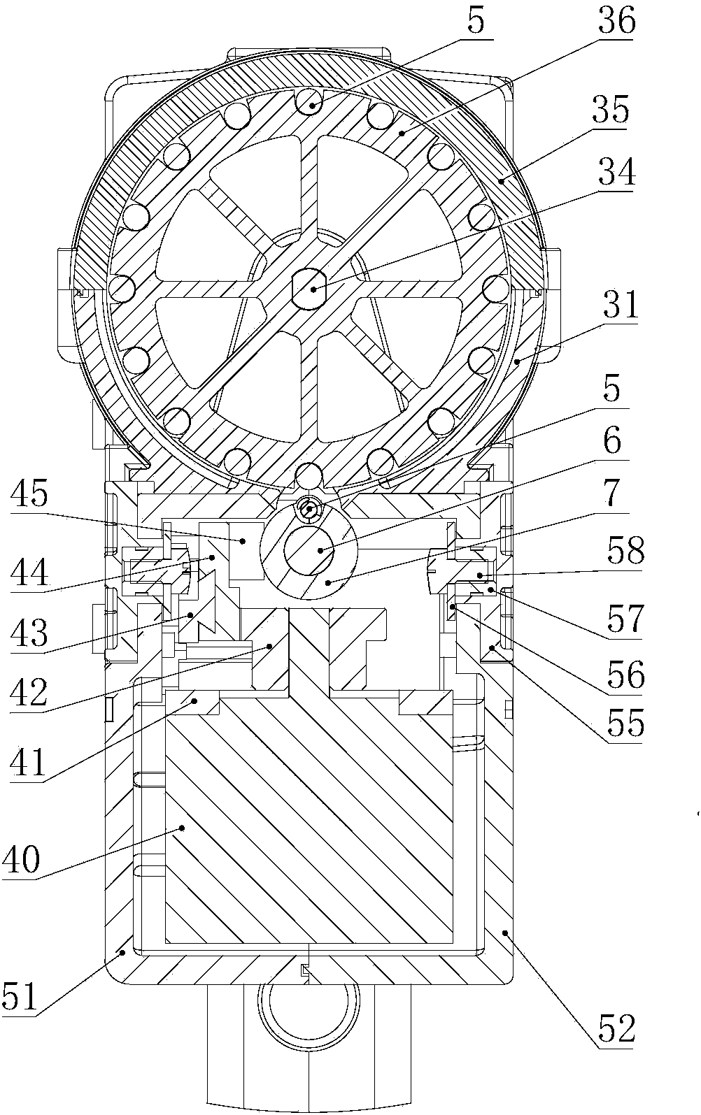
[0023] According to attached Figures 1 to 3 The specific embodiment of the present invention is described further:

[0024] A continuous firing stud welding torch includes a torch casing, a wheel mechanism, a first motor 38 , a second motor 40 , and a driven shaft 7 . The driven shaft 7 is wrapped with a radial magnetic steel 6, and the upper part of the driven shaft 7 is provided with a groove matching the diameter of the welding stud 5. The second motor 40 is fixedly connected with the gun housing through the motor base 41, and the output shaft of the second motor is sleeved with a gear 42, the gear 42 meshes with the rack slider 44, and the rack slider 44 is connected to the driven shaft through the connecting block 45. 7 connection, the rack slider and the guide rail 43 are clearance fit. Driven shaft 7, guide rail 43, rack slide block 44 and connection block 45 are all conductors, and guide rail 43 is connected with the negative pole of welding power supply 17, and the...


PUM


Abstract

The invention relates to a repeating stud welding torch, which comprises a torch casing, a rotary wheel mechanism, a first motor, a second motor and a driven shaft, wherein the interior of the driven shaft is coated with a radial magnetic steel or a radial electromagnet, and the top end of the driven shaft is provided with a groove which is matched with the diameter of a welding screw; the driven shaft is connected with the second motor, and the second motor drives the driven shaft to move; the front end of the torch casing is provided with a welding screw positioning mechanism; the rotary wheel mechanism comprises a rotary wheel, a shaft center of the rotary wheel is inserted with a core shaft, one end of the core shaft is connected with the first motor, the other end of the core shaft is rotationally connected with a rotary wheel seat, the periphery of the rotary wheel is provided with a plurality of concave openings at equal intervals, and each concave opening is matched with the diameter of each welding screw; the welding screws are sequentially inserted into the concave openings of the rotary wheel, the first motor drives the rotary wheel to rotate, the concave grooves are sequentially aligned with the groove of the driven shaft, the welding screws are absorbed to fall into the groove, and the driven shaft delivers the welding screws to the welding surface for welding. The welding torch has the advantages that the continuous welding is realized, the operation is convenient, and the welding efficiency is high.

Description

technical field [0001] The invention relates to a welding device, in particular to a continuous firing stud welding torch. Background technique [0002] At present, stud welding guns are widely used in automobiles, shipbuilding, aviation, boilers, locomotives and other sheet metal industries. Due to the simple structure of the existing stud welding guns, each welding stud is inserted from the head of the welding gun by the operator. , the operator's fingers will be very tired, therefore, the efficiency is low and the labor intensity is high. In addition, the existing screw welding torch can only weld one welding stud at a time, and when working on a large area, the efficiency is low and the work intensity is high. Contents of the invention [0003] In order to solve the deficiencies of the prior art, the invention provides a stud welding torch with a novel structure and easy use. The stud welding torch can quickly load a plurality of welding studs to realize continuous we...

Claims


Application Information

Patent Timeline
IPC IPC(8): B23K9/20B23K9/28
CPCB23K9/202B23K9/206
Inventor 毛世新胡刚
Owner 青岛艾特尔电源科技有限公司
Learn More