
Radial artery hemostatic device, control system and operation method thereof

A control system and hemostatic device technology, applied in tourniquets, medical science, surgery, etc., can solve the problems of inability to measure pressure, manual pressure adjustment, low reusability, etc., to avoid radial artery occlusion, prevent radial artery occlusion, Guaranteed hemostatic effect

Active Publication Date: 2016-04-20
上海微创龙脉医疗器材有限公司
View PDF9 Cites 0 Cited by
  • Summary
  • Abstract
  • Description
  • Claims
  • Application Information

AI Technical Summary

Problems solved by technology

The technical defect of this radial artery compressing device is: 1, this invention adopts the method of rotating pressure, the pressure value cannot be measured scientifically, and it is not convenient to find a suitable pressure value; 2, manual pressure release increases the work of medical staff
The defects of the radial artery forceps are: 1. Adopting the empirical setting method, the pressure cannot be measured, and it is not convenient to find the most suitable pressure; 2. The pressure is manually adjusted, which increases the work of medical staff
This method increases the workload of doctors and nurses
[0012] (3) Low reuse rate
Most of the current radial artery hemostats are for one-time use, and the reuse rate is low, which wastes resources and increases the economic pressure of patients
[0013] (4) Complex disinfection process
Even if some electronic radial artery hemostats can be reused, it will bring a complicated disinfection process, and the cost of disinfection is also high

Method used

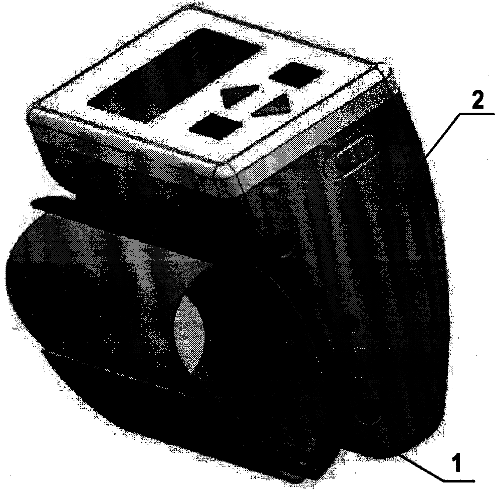
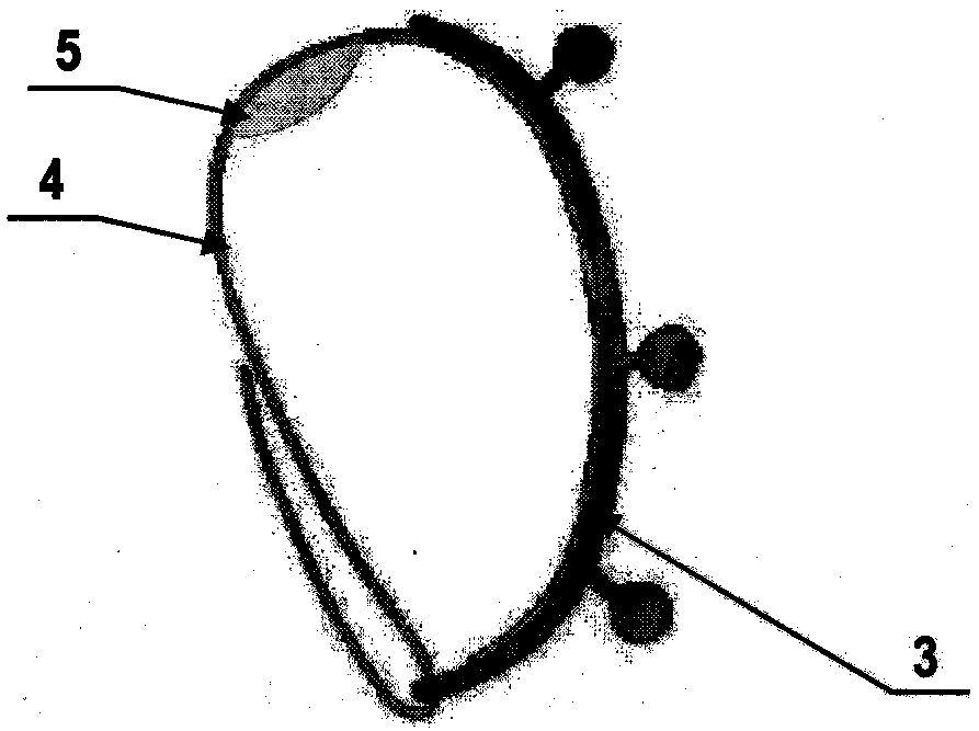

Image

  • Radial artery hemostatic device, control system and operation method thereof
  • Radial artery hemostatic device, control system and operation method thereof
  • Radial artery hemostatic device, control system and operation method thereof

Examples


Embodiment Construction

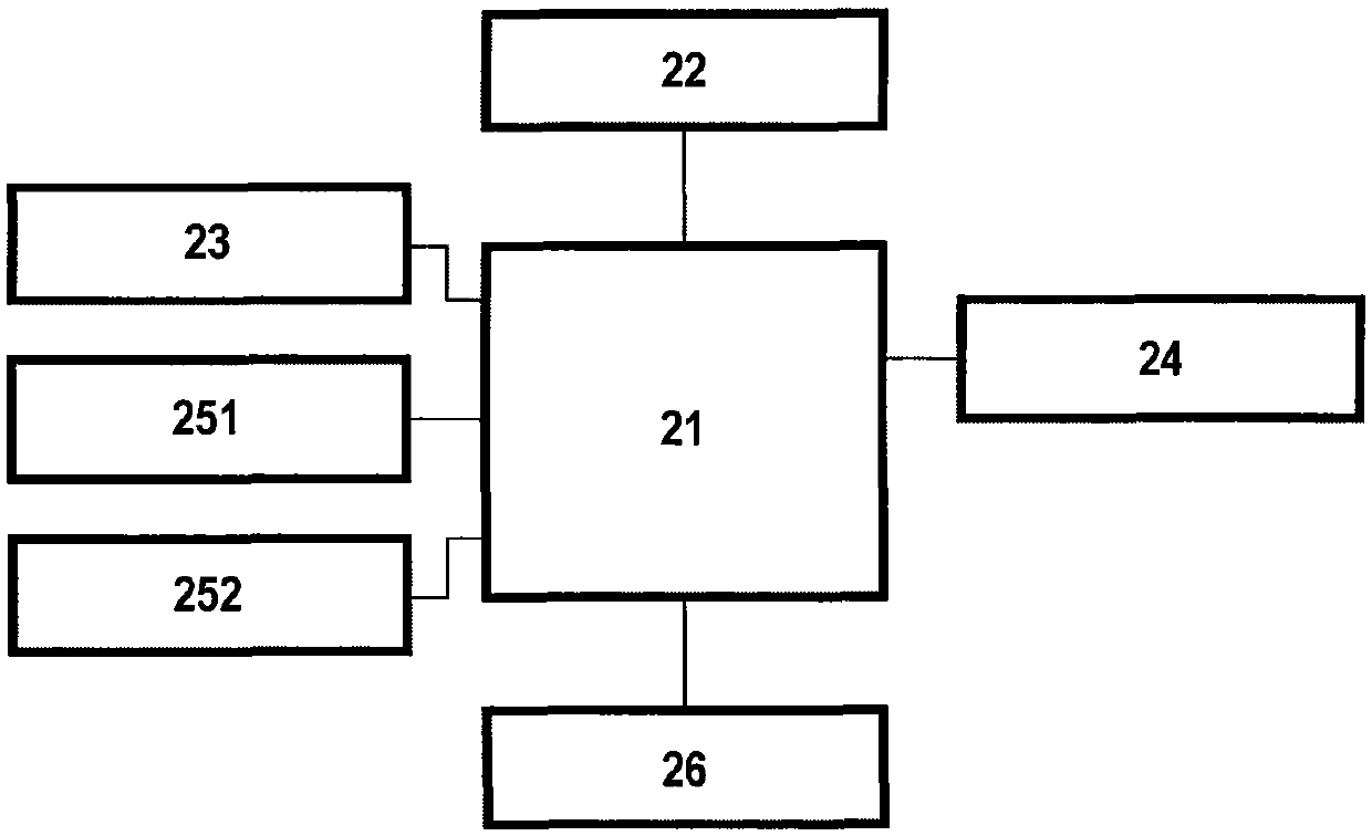
[0054] figure 1 Shows the block diagram of the control system of the radial artery hemostat of the present invention, the circuit mainly includes MCU21, the MCU21 is connected with a crystal oscillator unit 22, an input unit 23 for receiving signal instructions, a display control unit 24, and an output unit for controlling a pressure pump 251. An output unit 252 for controlling the solenoid valve, a sensor 26, and the like. Among them, the MCU21 can have a high-performance simplistic instruction set, and can be used in a wide range of applications. The MCU has rich function options such as low power consumption, flexible I / O, timer function, optional oscillation type, "watchdog" timer and low voltage reset, and has a very high cost performance. Preferably, the micro-control unit is a single-chip microcomputer control module, especially an ARM control module. In addition, the micro control unit can also be an FPGA control module or the like. The crystal oscillator unit 22 pr...


PUM


Abstract

The invention relates to a control system for a radial artery hemostat. The control system comprises a micro-control unit, a crystal oscillator unit, an input unit, a display control unit, a pressure pump control output unit, a solenoid valve control output unit and a sensor. The crystal oscillator unit, the input unit, the display control unit, the pressure pump control output unit, the solenoid valve control output unit and the sensor are all in communication with the micro-control unit mutually; the crystal oscillator unit provides a clock signal to the control system; the input unit receives the signal instruction and transmits the same to the micro-control unit; the sensor is used for measuring pressure value and then feeding measured pressure value back to the micro-control unit so as to realize closed-loop control to pressure. The invention further relates to the radial artery hemostat with the control system and a method for operating the radial artery hemostat. The control system can be used for controlling and operating the radial artery hemostat accurately to enable the radial artery hemostat to be capable of compressing automatically and decompressing periodically after vascular intervention diagnosis and surgery via the radial artery, being reused partially and realizing quantitative setting of the pressure value.

Description

technical field [0001] The invention relates to the field of disposable medical devices, in particular to a control system for a radial artery hemostat, a radial artery hemostat and a method for operating the radial artery hemostat with the control system. Background technique [0002] With the improvement of living standards, coronary heart disease has gradually become the main killer of human beings. Coronary artery interventional diagnosis and treatment has become one of the main means of diagnosis and treatment of coronary heart disease. At present, the interventional pathways for coronary interventional diagnosis and treatment are mainly divided into femoral artery and radial artery. In 1989, Canadian doctor Campeau pioneered percutaneous radial artery puncture for coronary angiography; in 1992, Dutch doctor Kiemenij reported the results of treatment using this approach. With the promotion and popularization of coronary artery interventional diagnosis and treatment ope...

Claims


Application Information

Patent Timeline
Patent Type & Authority Patents(China)
IPC IPC(8): A61B17/12
CPCA61B17/1355A61B2017/00132A61B2017/00199A61B2017/00544A61B2017/12004
Inventor 仪克晶刘智勇张久礼吕冬沈辉郝升旗
Owner 上海微创龙脉医疗器材有限公司
Learn More