
Magnetic resonance imaging apparatus and magnetic resonance imaging method

A technology of magnetic resonance imaging and magnetic resonance signals, which can be used in measurement devices, measurement of magnetic variables, medical science, etc., and can solve problems such as shortening the imaging time.

Active Publication Date: 2014-05-21
TOSHIBA MEDICAL SYST CORP
View PDF5 Cites 6 Cited by
  • Summary
  • Abstract
  • Description
  • Claims
  • Application Information

AI Technical Summary

Problems solved by technology

On the other hand, if the asymmetrical direction of the k-space data is used as the encoding direction, the imaging time will be shortened.

Method used


Image

  • Magnetic resonance imaging apparatus and magnetic resonance imaging method
  • Magnetic resonance imaging apparatus and magnetic resonance imaging method
  • Magnetic resonance imaging apparatus and magnetic resonance imaging method

Examples


Embodiment Construction

[0020] A magnetic resonance imaging apparatus and a magnetic resonance imaging method according to embodiments of the present invention will be described with reference to the drawings.

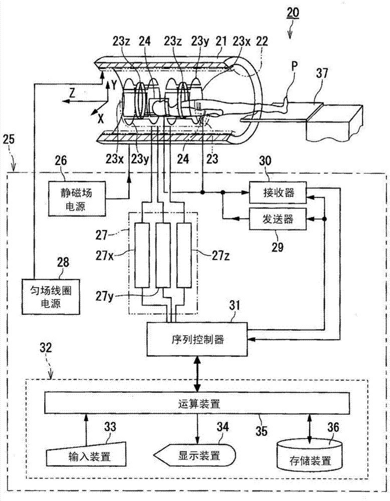
[0021] figure 1 It is a configuration diagram of a magnetic resonance imaging apparatus according to an embodiment of the present invention.

[0022] The magnetic resonance imaging apparatus 20 includes a cylindrical static magnetic field magnet 21 forming a static magnetic field, shim coils 22 , gradient magnetic field coils 23 , and RF coils 24 provided inside the static magnetic field magnet 21 .

[0023] In addition, the magnetic resonance imaging apparatus 20 includes a control system 25 . The control system 25 includes a static magnetic field power supply 26 , a gradient magnetic field power supply 27 , a shim coil power supply 28 , a transmitter 29 , a receiver 30 , a sequence controller 31 and a computer 32 . The gradient magnetic field power supply 27 of the control system 25 has a...


PUM


Abstract

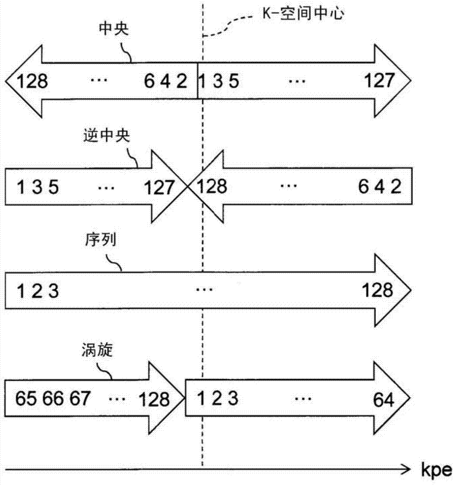
The magnetic resonance imaging apparatus of an embodiment is provided with a data-collecting unit and an image-generating unit. From the subject, the data-collecting unit collects multiple magnetic resonance signals corresponding to a sampling region that is asymmetric in the wavenumber direction in the k-space with a data collection sequence having a first regularity and a data collection sequence having a second regularity that differs from the first regularity. The image-generating unit generates magnetic resonance image data by data-processing that comprises signal filling into the non-sampling region using k-space phase conjugate symmetry and image reconstruction processing based on the multiple magnetic resonance signals.

Description

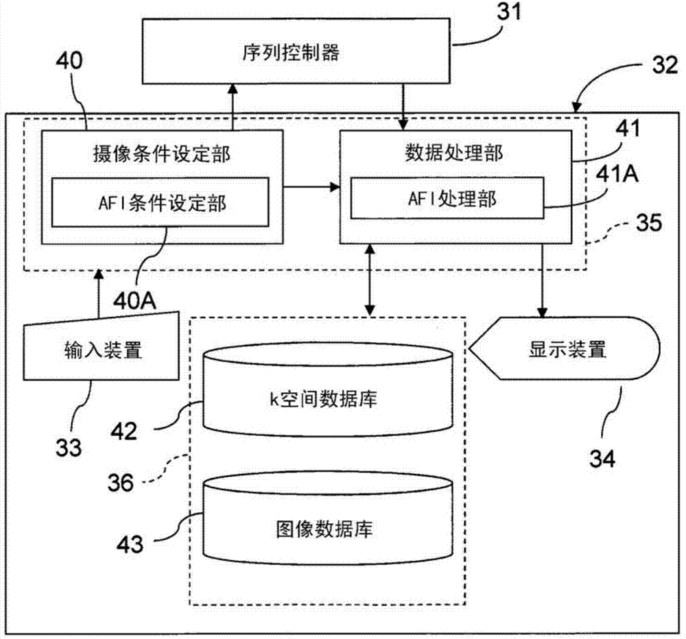
technical field [0001] Embodiments of the present invention relate to a magnetic resonance imaging (MRI: Magnetic Resonance Imaging) apparatus and a magnetic resonance imaging method. Background technique [0002] The MRI device is an image diagnostic device that magnetically excites the nuclear spins of the subject placed in a static magnetic field with a high-frequency (RF: radio frequency) signal of Larmor frequency. The resonance (MR: magnetic resonance) signal reconstructs the image. [0003] AFI (Asymmetric Fourier Imaging: Asymmetric Fourier Imaging) method is known as one of the imaging methods of the MRI apparatus. The AFI method is a method in which data is sampled so that it becomes asymmetrical in the wavenumber direction in k-space, and after phase correction is performed using the phase distribution estimated from the sampled own data, the image data is Do the refactoring. According to the AFI method, it is possible to generate image data equivalent to image...

Claims


Application Information

Patent Timeline
IPC IPC(8): A61B5/055
CPCG01R33/4818G01R33/482G01R33/5608G01R33/5617G01R33/565
Inventor 梅田匡朗坂下尚孝
Owner TOSHIBA MEDICAL SYST CORP
Learn More