
Camera module

A camera module and camera technology, applied in the information field, can solve problems such as difficult assembly of information terminals, low imaging quality, and large size

Inactive Publication Date: 2014-05-21
WUXI CINSEC INFORMATION TECH
View PDF3 Cites 5 Cited by
  • Summary
  • Abstract
  • Description
  • Claims
  • Application Information

AI Technical Summary

Problems solved by technology

[0006] However, the camera modules in the prior art generally have the deficiencies and defects of difficulty in assembling information terminals, excessive size, and low imaging quality.

Method used


Image

  • Camera module
  • Camera module
  • Camera module

Examples


Embodiment Construction

[0015] In order to make the technical means, creative features, goals and effects achieved by the present invention easy to understand, the present invention will be further described below in conjunction with specific illustrations.

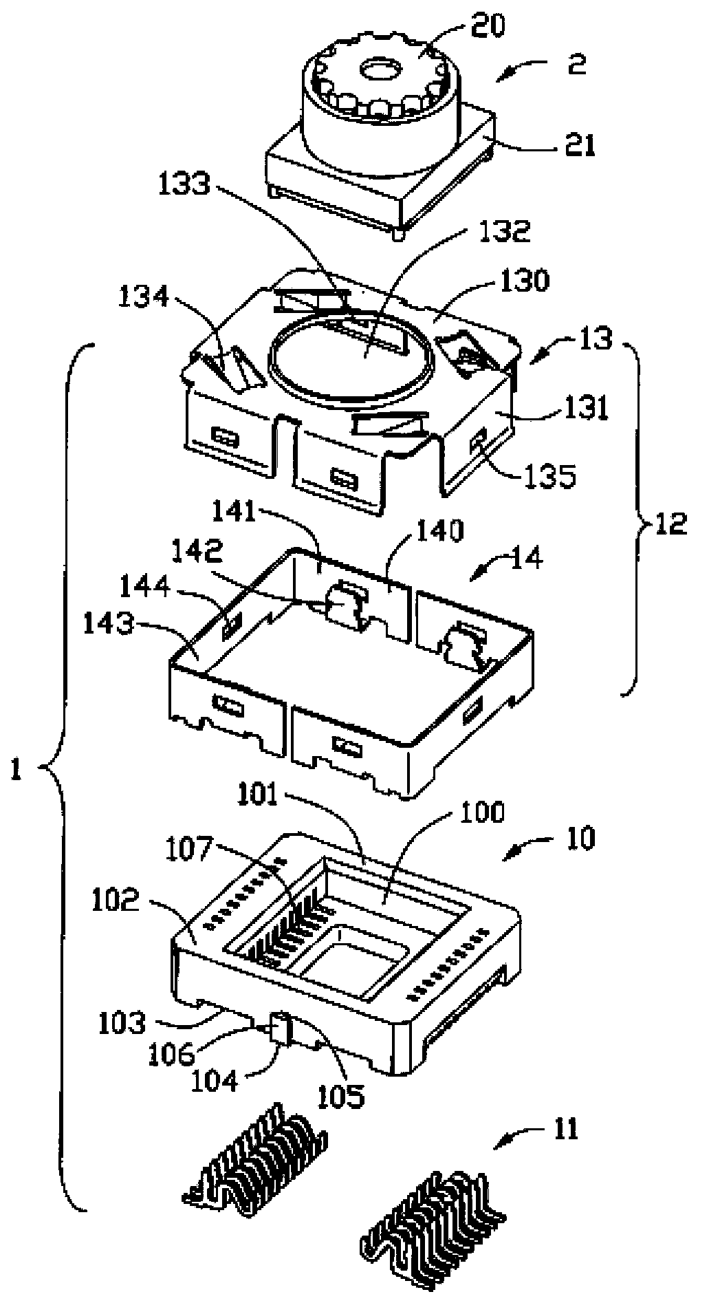
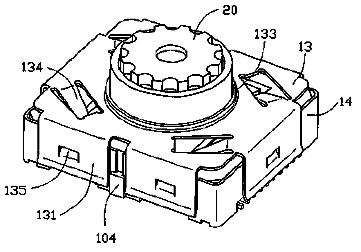
[0016] Figure 1 to Figure 2 An electrical connector 1 for a camera module of the present invention is disclosed.

[0017] See figure 1 As shown, the electrical connector 1 is installed on the circuit board of portable electronic devices such as mobile phones and PDAs, and is used to assemble the camera module 2 therein, including: an insulating body 10, a plurality of conductive terminals accommodated in the insulating body 10 11 and a shielding shell 12 covering the periphery of the insulating body 10.

[0018] The insulative body 10 is roughly in the shape of a cuboid, and a receiving space 100 is recessed in the middle of the upper surface for accommodating the body portion 21 of the camera module 2 . The receiving space 100 is surrounded...


PUM


Abstract

Disclosed is a camera module. The camera module comprises an electric coupler, and the electric coupler is mounted on a circuit board of a portable information terminal for assembling the camera module into the portable information terminal. The camera module is characterized by sequentially comprising a first meniscus lens with a focal distance of f1, a second meniscus lens with a focal distance of f2 and an image sensor for receiving an image; one surface of the second meniscus lens is provided with a binary optic structure; at least two surfaces of the first meniscus lens as well as the second meniscus lens are aspheric surfaces; f1 / f2 is between -0.85 and -2.3. The camera module is convenient to assemble with the portable information terminal, high in imaging quality and small in size.

Description

technical field [0001] The invention belongs to the field of information technology, and in particular relates to a camera module. Background technique [0002] Cameras are widely used in portable information terminals, and functional structure modularization is also an important trend in the development of modern integrated circuits. Many camera modules are disclosed in the prior art. [0003] Patent document CN2762161U discloses a camera module with a further reduced height, comprising: a substrate in the shape of a flat plate; a camera chip arranged on the substrate; a lens holder in a cylindrical structure, which contains an inner ring shoulder, the lens mount is connected to the base plate; the lens assembly is screwed into the cylindrical structure on the upper part of the inner ring shoulder of the lens mount; and the optical filter is bonded to the inner ring of the lens mount shoulder. On the basis of the traditional module, the utility model cancels the cavity st...

Claims


Application Information

Patent Timeline
IPC IPC(8): G02B7/02H04N5/225
Inventor 耿振民
Owner WUXI CINSEC INFORMATION TECH
Learn More