
Tool structure for measuring length of ring groove of plunger piston part

A technology of length measurement and plunger is applied in the field of tooling structure for measuring the length of the ring groove of the plunger, which can solve the problem of inability to meet the measurement, and achieve the effects of fast and convenient measurement, improved measurement efficiency, and fast and convenient positioning.

Active Publication Date: 2014-05-21
无锡威孚马山油泵油嘴有限公司
View PDF6 Cites 0 Cited by
  • Summary
  • Abstract
  • Description
  • Claims
  • Application Information

AI Technical Summary

Problems solved by technology

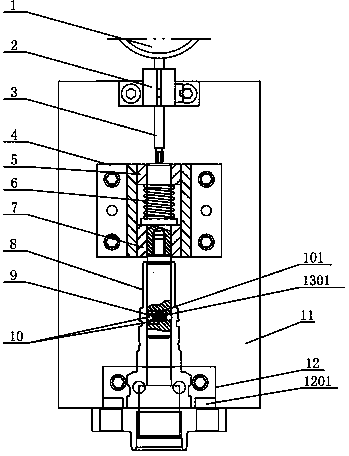
At present, the inner ring of the existing plunger sleeve generally needs to be machined with a ring groove. In order to meet the size requirements of the product drawing, the distance between the ring groove and the end face of the plunger sleeve needs to be measured. The existing tooling cannot meet the measurement of the above dimensions. , so it is urgent to design a new tooling structure

Method used


Image

  • Tool structure for measuring length of ring groove of plunger piston part
  • Tool structure for measuring length of ring groove of plunger piston part

Examples


Embodiment Construction

[0016] The specific implementation manner of the present invention will be described below in conjunction with the accompanying drawings.

[0017] Such as figure 1 , figure 2 As shown, a tooling structure for measuring the length of the plunger ring groove includes a chassis 11, and the bracket 4 and the chassis 11 are fixed through positioning pins and fasteners (the positioning pins and fasteners are not marked in the figure) , the positioning mandrel 13 penetrates the device in the bracket 4 and is located in the bracket 4. The first bushing 5 and the second bushing 7 are respectively set on the positioning mandrel 13, and the first bushing 5 and the second bushing are located on the positioning mandrel 13. 7, the first spring 6 is also installed on the positioning mandrel 13; the steel ball 10 is installed symmetrically within the positioning mandrel 13, and the second spring 9 is connected between the two steel balls 10. On the positioning mandrel 13, there is a throug...


PUM


Abstract

The invention relates to a tool structure for measuring the length of a ring groove of a plunger piston part. The tool structure comprises a chassis, wherein a support is fixedly connected with the chassis, a positioning mandrel penetrates the support and is located in the support, respectively sleeved by a first lining and a second lining and located between the first lining and the second lining, and a first spring is further arranged on the positioning mandrel. Steel balls are symmetrically arranged inside the positioning mandrel, and a second spring is connected between two steel balls. The tool structure is simple in structure and quick and convenient to measure, embedding connection of the ring groove of an inner ring of a plunger sleeve is achieved by utilizing the steel balls symmetrically arranged in the positioning mandrel, positioning is quick and convenient, a measurement standard of the plunger sleeve is effectively achieved by utilizing a blocking plate, measurement of a distance between the ring groove of the plunger sleeve and the end face is achieved, the time and labor are saved, the measurement efficiency is greatly improved, and the enterprise cost is saved.

Description

technical field [0001] The invention relates to a tooling, in particular to a tooling structure for measuring the length of a ring groove of a plunger. Background technique [0002] The plunger couple is formed by the precision fit of the plunger and the plunger sleeve, and the oil outlet valve couple (composed of the oil outlet valve and the oil outlet valve seat) is installed above it. The plunger can be divided into different types according to the applicable fuel injection pump. Type A, Type B, Type K, Type AD, Type P, etc., to meet the needs of different diesel engines. At present, the inner ring of the existing plunger sleeve generally needs to be machined with a ring groove. In order to meet the size requirements of the product drawing, the distance between the ring groove and the end face of the plunger sleeve needs to be measured. The existing tooling cannot meet the measurement of the above dimensions. , so it is urgent to design a new tooling structure. Con...

Claims


Application Information

Patent Timeline
Patent Type & Authority Applications(China)
IPC IPC(8): G01B5/02G01B5/14
Inventor 朱仁义
Owner 无锡威孚马山油泵油嘴有限公司
Learn More