Coordinated type smoke duct air door

A flue gas duct and linkage technology, which is applied in the field of flue gas duct dampers, can solve the problems of not being able to open or close the fan blades, troublesome operation, etc.

Inactive Publication Date: 2014-05-21
江苏中纤管道设备有限公司
View PDF0 Cites 2 Cited by
  • Summary
  • Abstract
  • Description
  • Claims
  • Application Information

AI Technical Summary

Problems solved by technology

When the smoke duct damper in the prior art is in use, the fan blades cannot be opened or closed in a linked manner, and the operation is troublesome

Method used


Image

  • Coordinated type smoke duct air door
  • Coordinated type smoke duct air door
  • Coordinated type smoke duct air door

Examples


Embodiment Construction

[0010] The present invention will be further described below according to the accompanying drawings and in conjunction with the embodiments.

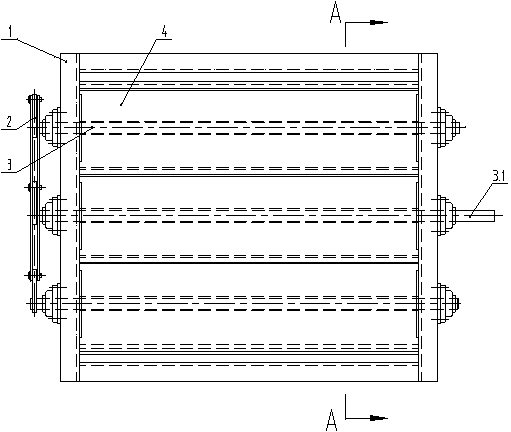
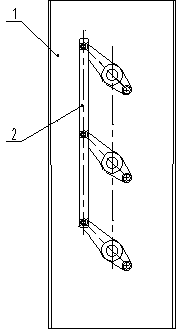
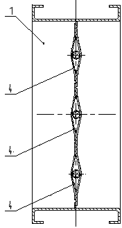
[0011] The linked flue air door shown in the drawings includes a frame 1, a fan blade 4, a fan blade support shaft 3, and a connecting rod mechanism 2. The fan blade 4 is installed in the frame 1 through the fan blade support shaft 3, and the fan blade 4 is at least There are two; the linkage mechanism 2 is connected with the fan blade support shaft 3; one of the fan blade support shafts 3 is a drive shaft 3.1.

[0012] The present invention drives the link mechanism 2 through the drive shaft 3.1, and the link mechanism 2 drives the fan blade support shaft 3 to open or close the fan blade 4 quickly.


PUM


Abstract

The invention discloses a coordinated type smoke duct air door, comprising a frame, at least two fan blades, blade supporting shafts and a link mechanism, wherein the fan blades are mounted in the frame by the fan blade supporting shafts; the link mechanism is connected with the fan blade supporting shafts; one of the fan blade supporting shafts is a driving shaft. The link mechanism is driven by the driving shaft, and the fan blades are rapidly opened or closed through driving the fan blade supporting shafts by the link mechanism.

Description

technical field [0001] The invention relates to a smoke air duct damper. Background technique [0002] The air door of the smoke duct generally includes a frame, a fan blade, and a fan blade support shaft. There are at least two fan blades, and the fan blade is installed in the frame through the fan blade support shaft. When the smoke duct damper in the prior art is in use, the fan blades cannot be opened or closed in a linked manner, and the operation is troublesome. Contents of the invention [0003] The present invention aims at the deficiencies of the prior art, and provides a linkage-type smoke air duct damper which adopts a linkage manner to quickly open or close the fan blades. [0004] The present invention achieves technical goals through the following technical solutions. [0005] The interlocking smoke duct air door includes a frame, fan blades, and fan blade support shafts; the fan blades are installed in the frame through the fan blade support shafts; there ...

Claims


Application Information

Patent Timeline
IPC IPC(8): F23J13/08
Inventor 金伟翟根林李云忠
Owner 江苏中纤管道设备有限公司
Why Eureka
Try Eureka