
Solar lighting system

A lighting system and solar energy technology, applied in the field of solar energy, can solve problems such as consumption

Inactive Publication Date: 2014-05-21
FOSHAN LATTICE ENERGY TECH CORP
View PDF4 Cites 5 Cited by
  • Summary
  • Abstract
  • Description
  • Claims
  • Application Information

AI Technical Summary

Problems solved by technology

These methods all need to consume considerable power, although lighting equipment is constantly improved to save power consumption

Method used


Image

  • Solar lighting system
  • Solar lighting system
  • Solar lighting system

Examples


Embodiment Construction

[0011] In order to make the object, technical solution and advantages of the present invention clearer, the present invention will be further described in detail below in conjunction with the accompanying drawings.

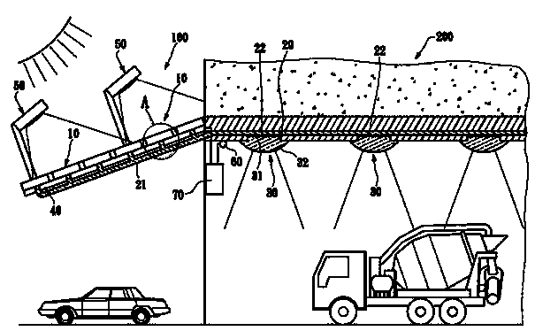
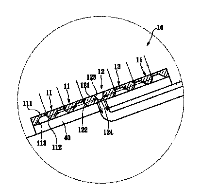
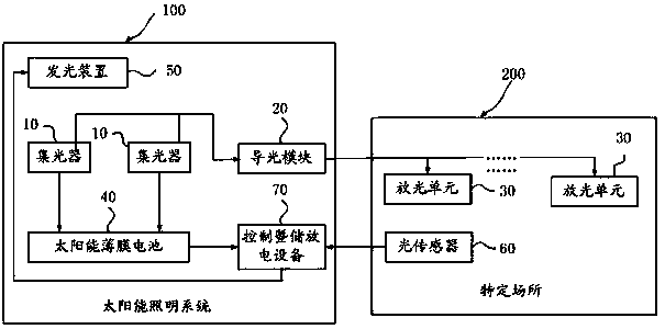
[0012] Please refer to figure 1 , is a schematic side view of the solar lighting system of the present invention. A solar lighting system 100 of the present invention is used to provide light to a specific place 200. The solar lighting system 100 includes at least one light collector 10, a light guide module 20, at least one light emitting unit 30, and at least one solar film The battery 40 and at least one light emitting device 50 .

[0013] The light guide module 20 is connected to the at least one light collector 10 for guiding the light received by the at least one light collector 10 . The at least one light emitting unit 30 is connected to the light guide module 20 and placed in the specific location for emitting light guided by the light guide module 20 . ...


PUM


Abstract

The invention discloses a solar lighting system, which is used for providing light rays to a specified place, and comprises at least one light collector, a light guide module, at least one light releasing unit, at least one solar film cell, at least one piece of control and electricity storage and discharge equipment and at least one light emitting unit, wherein the light collector is arranged outside the specific place for receiving outside light rays, the light guide module is connected with the light collector for guiding to transmit the received light rays, the light releasing unit is connected with the light guide module and is arranged inside the specific place for releasing the light rays conducted by the light guide module, the solar film cell is arranged below the light collector for receiving light rays transmitting the light collector, converting the light rays into electricity energy and storing the electricity energy in the control and electricity storage and discharge equipment, and the light emitting device is arranged above the light collector for providing light rays to the light collector through conversion of the electricity when external light rays are insufficient. After the solar lighting system is adopted, natural light of sun can be utilized for providing lighting to the needed specified place, so that the electricity energy is saved.

Description

technical field [0001] The invention relates to the technical field of solar energy, in particular to a solar lighting system. Background technique [0002] Observe that all current place lighting, including tunnels, parking lots, indoor lighting, greenhouse lighting, etc., use electric energy to convert into light to provide the required lighting. These methods all need to consume a considerable amount of electric energy, although the lighting equipment is constantly improved to save the consumed electric energy. However, power consumption is still unavoidable. [0003] In view of this, the inventor of the present invention feels that the above problems can be improved, so he devotes himself to research and cooperates with the application of theories to propose the present invention. Contents of the invention [0004] The technical problem to be solved by the present invention is to provide a solar lighting system, which uses the natural light of the sun to guide and...

Claims


Application Information

Patent Timeline
Patent Type & Authority Applications(China)
IPC IPC(8): F21S19/00F21V17/00
Inventor 简达益许海音陈冠宇胡芬绫李伟裕李昆益林晏瑞陈建君高千勋林旻翰郭佳瑜曾诗涵张勤煜
Owner FOSHAN LATTICE ENERGY TECH CORP
Learn More