Prismatic irregular hole underwater laser shock peening method and device for realizing same
A laser shock strengthening and impact strengthening technology, which is applied in the underwater laser shock strengthening of prismatic special-shaped holes and the strengthening of the inner wall and hole edge area of prismatic special-shaped holes, which can solve the problem of uneven stress distribution in the strengthened area of prismatic special-shaped holes and hinder laser beam irradiation. To the edge and corner area, affecting the laser shock strengthening and other problems, to achieve the effect of improving the service life, reducing the number of times, and saving energy
- Summary
- Abstract
- Description
- Claims
- Application Information
AI Technical Summary
Problems solved by technology
Method used
Image
Examples
Embodiment 1
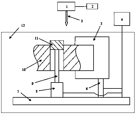
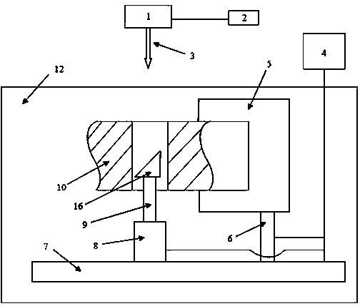
[0046] A device for laser shock strengthening of prismatic special-shaped holes, such as figure 1 and image 3 Shown are the laser shock peening of the edge area of the prism special-shaped hole and the laser shock peening of the inner wall; including: laser 1, laser control device 2, numerical control system 4, fixture Ⅰ 5, feeding device Ⅰ 6, five-axis table 7, Feeding device Ⅱ 8, fixture Ⅱ 9, cooperating pin 11, water tank 12 and total reflection mirror 16, this device can avoid hole edge to collapse and Figure 5 The "plasma shielding" effect shown.
[0047] The laser 1 is located directly above the five-axis table 7; the laser control device 2 is located on the right of the laser 1; the numerical control system 4 is located at the bottom right of the laser control device 2; the fixture I5 is connected to the five-axis table 7 through the feeding device I6; the fixture II9 It is connected to the five-axis table 7 through the feeding device II8; the matching pin 11 o...
Embodiment 2
[0050] The specific steps of laser shock strengthening in the edge area of prismatic special-shaped holes are as follows:
[0051] 1) Put the five-axis table 7 in the water tank 12.
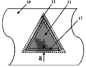
[0052] 2) Install the workpiece 2 on the fixture Ⅰ5, and paste such as Figure 7 Thicken the absorbing layer as shown, then install the matching pin 11 on the fixture Ⅱ9, adjust the feeding device Ⅰ6 and feeding device Ⅱ8 through the numerical control system to make the matching pin 11 and the prismatic special-shaped hole precisely match, the minimum interference is 0.01 mm , the maximum interference is 0.025 mm, and the upper end surface of the matching pin 11 coincides with the upper end surface of the prismatic shaped hole.
[0053] 3) Set the side length of the square laser beam of laser 1 to 3 mm, the pulse energy to 2 J and the pulse width to 20 ns through the laser control device 2.
[0054] 4) Adjust the five-axis worktable 7 through the numerical control system 4 to make the edge ar...
Embodiment 3
[0065] Change the square spot laser beam in the angular area 14 in Embodiment 2 to: the side length is 0.5-3 mm, the pulse energy is 1 J, and the pulse width is 20 ns, and other methods and steps remain unchanged.
PUM
| Property | Measurement | Unit |
|---|---|---|
| thickness | aaaaa | aaaaa |
Abstract
Description
Claims
Application Information
 - R&D
- Intellectual Property
- Life Sciences
- Materials
- Tech Scout
- Unparalleled Data Quality
- Higher Quality Content
- 60% Fewer Hallucinations
Browse by: Latest US Patents, China's latest patents, Technical Efficacy Thesaurus, Application Domain, Technology Topic, Popular Technical Reports.
© 2025 PatSnap. All rights reserved.Legal|Privacy policy|Modern Slavery Act Transparency Statement|Sitemap|About US| Contact US: help@patsnap.com


