
A kind of hydrogen peroxide extraction process

A hydrogen peroxide, process technology, applied in the directions of peroxide/peroxyhydrate/peroxyacid/superoxide/ozone, inorganic chemistry, non-metallic elements, etc., can solve the problem of low perforation rate, extraction tower accumulation, The problem of high viscosity of the working fluid can improve the efficiency of the tray, increase the mass transfer rate, and improve the extraction effect.

Active Publication Date: 2015-09-30
CHINA PETROLEUM & CHEM CORP +1
View PDF4 Cites 0 Cited by
  • Summary
  • Abstract
  • Description
  • Claims
  • Application Information

AI Technical Summary

Problems solved by technology

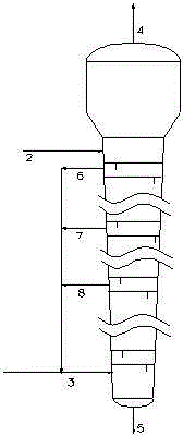
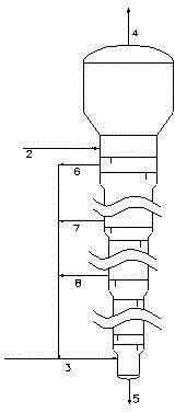
[0004] At present, the effect of the existing hydrogen peroxide extraction process is not particularly ideal, and there are several problems in operation: (1) It is difficult to grasp the opening area of ​​the sieve plate. If the opening area is large, the dispersed phase working liquid will pass through the sieve plate When the perforation rate is low, the mass transfer rate of the two phases is low, and the extraction effect is not ideal; if the opening area is small, it will easily cause the extraction tower to accumulate material, and the device cannot be operated; (2) due to the weight of the upper, middle and lower parts of the extraction tower The difference in specific gravity between the two phases will result in a difference in the driving force for mass transfer. The difference in specific gravity between the light and heavy phases at the bottom of the extraction tower is the largest, and the driving force is the largest. According to theoretical analysis, the flow rate of the working liquid in the upper part of the extraction tower passing through the sieve hole is smaller, while the flow rate of the working liquid in the lower part through the sieve hole is larger, which requires that the opening area of ​​the lower part of the extraction tower is smaller, while the upper part is larger. The opening area is larger, but in fact, many manufacturers only set two specifications for the sieve plate of the extraction tower, one for the upper part and one for the lower part. (3) During normal extraction operation, due to the thick liquid layer under the sieve plate on the upper part of the extraction tower and the high viscosity of the working fluid, it is easy to produce material accumulation in the extraction tower, which will affect the normal operation of the device; (4) The operating flexibility of the device is small. When the operating load changes, since the perforation flow rate of the working fluid in the extraction tower has an optimal effect range, when the flow rate of the working fluid changes, the flow rate in the extraction tower will change, which will affect the two-phase mass transfer. speed, making the extraction effect worse
However, since the sieve plates of the extraction tower in the prior art generally have about 50 to 60 layers, when the opening area increases layer by layer from bottom to top, because the difference between the upper and lower plates is too small, there are certain difficulties in industrial realization.
In addition, this method does not fundamentally solve the problems of unsatisfactory extraction effect and material accumulation when the operating load of the device changes.

Method used


Image

  • A kind of hydrogen peroxide extraction process
  • A kind of hydrogen peroxide extraction process

Examples


Embodiment 1

[0029] When the extraction tower is used at 100% operating load, the volume flow rate of the working fluid drawn from the production pipeline gradually increases by 4% from bottom to top, and the volume flow ratio of the total working fluid drawn out to the oxidation liquid feed is 1:80, return At the inlet of the oxidation liquid at the bottom of the extraction tower, after this process, the mass fraction of hydrogen peroxide at the bottom of the extraction tower is 29.8% to 33.5%, and the residual hydrogen peroxide content in the raffinate at the top of the extraction tower is 0.12g / L to 0.20g / L; The total amount of working fluid drawn, so that the volume flow ratio of the total working fluid drawn and the oxidized liquid feed is 1:20, and returned to the inlet of the oxidized liquid at the bottom of the extraction tower. After this process, the flow state in each layer of the extraction tower Stable, the working fluid floats evenly, the mass fraction of hydrogen peroxide at ...

Embodiment 2

[0031]When the extraction tower is used at 100% operating load, there are 4 extraction pipelines from the 25th, 30th, 35th, and 40th sieve plate positions respectively, and the volume flow rate of the working fluid drawn from the extraction pipelines gradually increases from bottom to top. Increase by 2.5%, the volume flow ratio of the total amount of working liquid drawn to the feed of the oxidizing liquid is 1:80, and return to the inlet of the oxidizing liquid at the bottom of the extraction tower. After this process, the mass fraction of hydrogen peroxide at the bottom of the extraction tower is 29.2%~ 31.5%, the residual hydrogen peroxide content in the overhead raffinate of the extraction tower is 0.12g / L~0.20g / L; change the total amount of working fluid drawn, so that the volume flow ratio of the total working fluid drawn and the oxidizing liquid feed is 1: 10. The volume flow rate of the working fluid drawn out from the extraction pipeline gradually increases by 1.0% fr...


PUM

PropertyMeasurementUnit
diameteraaaaaaaaaa
diameteraaaaaaaaaa
quality scoreaaaaaaaaaa

Abstract

The invention discloses a hydrogen peroxide extraction process which comprises the following contents: countercurrent extraction separation of oxidized liquid is carried out in an extraction column, wherein the oxidized liquid is obtained in a hydrogen peroxide production process by an anthraquinone method; the extraction column is a plate column, and an operating fluid extraction pipeline is disposed below at least one column plate; the extracted operating fluid is circulated to the lower part of the extraction column, and is subjected to extraction separation with the oxidized liquid. The process has the advantages of good extraction effect, large adjustable range of device load, stable operation, no liability to material deposition, and suitability for industrial application.

Description

technical field [0001] The invention relates to a hydrogen peroxide extraction process, in particular to a hydrogen peroxide extraction process for improving the extraction effect. Background technique [0002] Hydrogen peroxide ( H 2 o 2 Aqueous solution) is an important inorganic chemical product. Because the final product after its application is water and oxygen, it has no pollution to the environment, so it is called a green chemical product and is widely used. At present, the industrial production of hydrogen peroxide in the world mainly adopts the anthraquinone method. The process of producing hydrogen peroxide by the anthraquinone method uses 2-ethylanthraquinone (EAQ) as the working carrier, and heavy aromatics (Ar) and trioctyl phosphate (TOP) as the solvent. It is made into a working solution and undergoes several processes of hydrogenation, oxidation, extraction and post-treatment of the working solution. [0003] The extraction process occupies a pivotal posi...

Claims


Application Information

Patent Timeline
Patent Type & Authority Patents(China)
IPC IPC(8): C01B15/023
Inventor 张英杨秀娜齐慧敏高景山
Owner CHINA PETROLEUM & CHEM CORP
Learn More