
A drill die structure for machining plunger oblique holes

A technology of drilling dies and inclined holes, which is applied to the drilling dies for workpieces and other directions, can solve the problems of high difficulty and high processing requirements, and achieve the effects of improving production efficiency, realizing processing and simple structure.

Active Publication Date: 2016-03-09
无锡威孚马山油泵油嘴有限公司
View PDF3 Cites 0 Cited by
  • Summary
  • Abstract
  • Description
  • Claims
  • Application Information

AI Technical Summary

Problems solved by technology

At present, according to the requirements of product drawings, it is necessary to process two symmetrical inclined holes connected to the middle hole of the plunger sleeve on the waist of the plunger. Since the inclined holes are inclined at a certain angle, the processing requirements are high and difficult, so there is an urgent need Design a Drilling Die Structure for Machining Plunger Inclined Holes

Method used


Image

  • A drill die structure for machining plunger oblique holes
  • A drill die structure for machining plunger oblique holes

Examples


Embodiment Construction

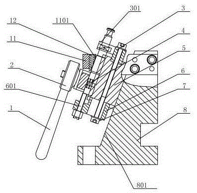
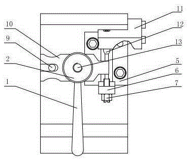
[0016] The specific implementation manner of the present invention will be described below in conjunction with the accompanying drawings.

[0017] like figure 1 , figure 2 As shown, a jig structure for processing inclined holes in a plunger includes a jig body 8 on which a first inclined surface 801 is formed. Drill template 11 and pressing plate 10 are respectively installed on the drill template body 8. One end of the drill template 11 extends to the side of the drill template body 8, and is affixed to the drill template body 8 by fasteners and pins, and is positioned in the drill template 11. Drill sleeve 12 , the drill sleeve 12 is tangent to the lower end surface of the drill template 11 to form a second slope 1101 . The pressure plate 10 is connected to the template body 8 through the support nail 9, and the spring 4 is also sleeved on the periphery of the support nail 9. One end of the screw rod 13 passes through the pressure plate 10 and is connected with the templa...


PUM


Abstract

The invention relates to a drill jig structure for machining a plunger hole. The drill jig structure comprises a drill jig body, wherein a drill template and a pressure plate are respectively arranged on the drill jig body; a positioning block is fixedly connected to the drill jig body; the two ends of the drill jig body are fixedly connected with a first positioning plate and a second positioning plate respectively. The drill jig structure is simple in structure and convenient to mount, base positioning of a flat surface of the plunger is effectively realized by using the first positioning plate, and then secondary positioning is realized by using a second positioning plate and a positioning bolt; a V-shaped surface is formed on the positioning block, so that the installation stability of the plunger is effectively realized, pressing assembly of the plunger is realized by the pressure plate, the pressure plate is flexibly adjusted by the arrangement of a screw, large-scale machining for plunger holes is effectively realized, and the production efficiency is improved.

Description

technical field [0001] The invention relates to processing equipment, in particular to a drilling mold structure for processing inclined holes of plungers. Background technique [0002] The plunger couple is formed by the precision fit of the plunger and the plunger sleeve, and the oil outlet valve couple (composed of the oil outlet valve and the oil outlet valve seat) is installed above it. The plunger can be divided into different types according to the applicable fuel injection pump. Type A, Type B, Type K, Type AD, Type P, etc., to meet the needs of different diesel engines. At present, according to the requirements of product drawings, it is necessary to process two symmetrical inclined holes connected to the middle hole of the plunger sleeve on the waist of the plunger. Since the inclined holes are inclined at a certain angle, the processing requirements are high and difficult, so there is an urgent need Design a drilling jig structure for machining the inclined hole ...

Claims


Application Information

Patent Timeline
Patent Type & Authority Patents(China)
IPC IPC(8): B23B47/28
CPCB23B47/281
Inventor 徐俊伟
Owner 无锡威孚马山油泵油嘴有限公司
Learn More